Eureka AIR delivers breakthrough ideas for toughest innovation challenges, trusted by R&D personnel around the world.

Translucent reflective type liquid crystal display

Inactive Publication Date: 2005-12-01
PANASONIC LIQUID CRYSTAL DISPLAY CO LTD +1
View PDF1 Cites 22 Cited by
  • Summary
  • Abstract
  • Description
  • Claims
  • Application Information

AI Technical Summary

Benefits of technology

[0005] The transflective color liquid crystal display according to these conventional technologies has an improved light use efficiency by forming a reflection film only on an optimum slope surface of a convex / concave portion made of resin or the like and formed on TFT, and the other area is used as a transmission portion.

Problems solved by technology

However, these conventional technologies are associated with some problems.
Since the reflection film is formed only on the optimum slope surface of the convex / concave portion, the cost rises because an additional photo mask and an additional patterning process are used for forming the reflection film only in this particular area, and moreover the aperture factor of the transmission portion and the reflection characteristics change with a position alignment precision of the photo mask and the convex / concave portion pattern.
These conventional technologies are also associated with another problem.
The cost rises therefore because of the complicated structure and manufacture processes.

Method used


Image

  • Translucent reflective type liquid crystal display
  • Translucent reflective type liquid crystal display
  • Translucent reflective type liquid crystal display

Examples


first embodiment

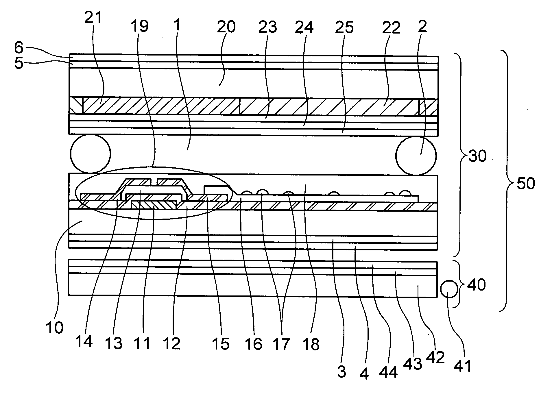
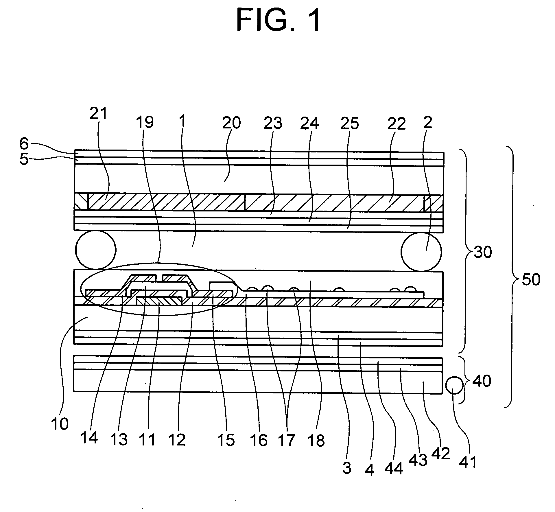
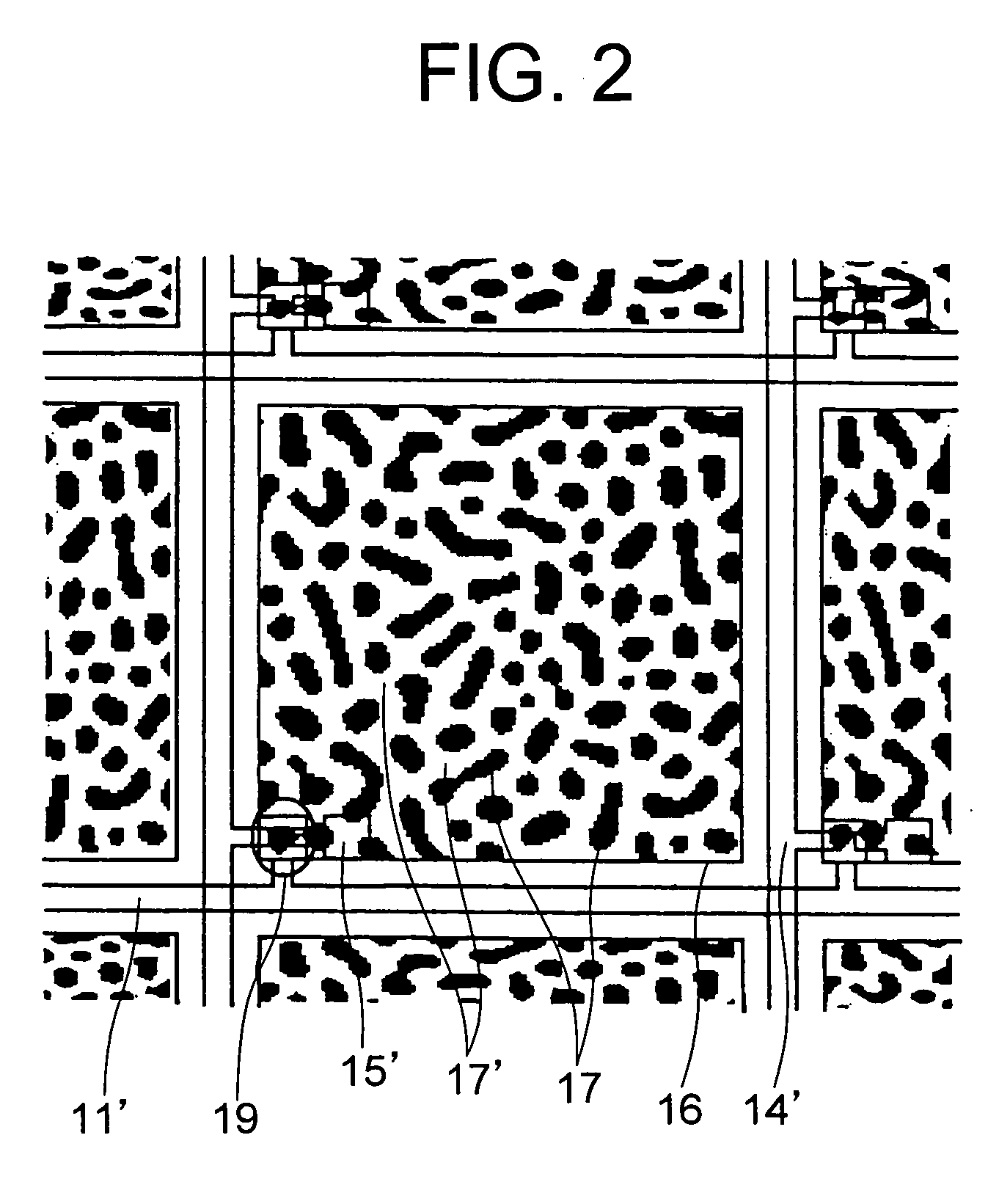
[0038] FIGS. 1 to 5 show a transflective liquid crystal display having transflective electrodes each constituted of convex or concave conductive members having a reflection function disposed at a desired density on each pixel electrode made of a transparent conductive layer.

[0039] First, the cross sectional structure of the transflective liquid crystal display of the present invention will be described.

[0040] As shown in FIG. 1, a plurality of TFT's 19 are disposed on a glass substrate 10 by vacuum vapor deposition and photolithography. TFT 19 is constituted of a gate electrode 11 (material: chromium, film thickness: 100 to 300 nm, preferably 150 nm), a gate insulating film 12 (material: silicon nitride, film thickness: 50 to 300 nm, preferably 200 nm), an amorphous silicon layer 13 doped with n-type impurities and phosphorus (material: amorphous silicon, film thickness: 10 to 100 nm, preferably 20 nm), a drain electrode 14 (material: chromium, film thickness: 100 to 300 nm, prefe...

second embodiment

[0059] Another embodiment of the present invention is shown in FIG. 7.

[0060] The different point of this embodiment from the first embodiment resides in that a pixel electrode 66 is electrically connected to the source electrode 65 of TFT via a contact hole formed through a protective film 68 disposed above TFT. In this embodiment, an orientation film 69 is disposed on the pixel electrode 66 or protective film 68.

[0061] The structure of the pixel electrode portion, the layout pattern of the conductive members and the structure of a transflective type liquid crystal display are the same as those of the first embodiment, and the detailed description thereof is omitted. This embodiment also has similar advantages to those of the first embodiment.

[0062] According to this embodiment, not only a liquid crystal display device can be manufactured by using current manufacture facilities and processes, but also a high quality image can be displayed both in transmission and reflection displ...

third embodiment

[0063]FIG. 8 shows a transflective liquid crystal display of a passive type having transflective electrodes each constituted of convex or concave conductive members having a reflection function disposed at a desired density on each pixel electrode made of a transparent conductive layer.

[0064] The display shown in FIG. 8 is a general transflective liquid crystal display of a passive type, excepting the following point. In FIG. 8, conductive members 82 are formed on and electrically connected to one transparent electrode 81. The material of the transparent electrode 81 is ITO having a film thickness of 100 to 300 nm, preferably 150 nm. The material of the conductive member is silver, a silver dust diameter is 1 to 10 μm, preferably 3 to 5 μm and a silver particle diameter is 1 to 20 nm, preferably 3 to 10 nm. Similar to the first embodiment, also in this embodiment, a TCP mounted with a liquid crystal driver IC, and an external driver circuit and the like are connected to a transflec...


PUM


Abstract

A low cost transflective type liquid crystal display is provided which can display a bright image with high contrast under both indoor and outdoor illumination environments. The liquid crystal display performing transmission type display and reflection type display, includes: a plurality of pixels surrounded on a substrate 10 by a plurality of gate electrodes 11 and a plurality of source electrodes 15 arranged perpendicularly to the gate electrodes; a switching element 19 arranged in each pixel and disposed neat at the intersection between each gate electrode and each source electrode; and a pixel electrode 16 connected to the switching element, wherein the pixel electrode is constituted of a transparent conductive layer and a conductive member 17 having a light reflection function and electrically connected to the transparent conductive layer.

Description

TECHNICAL FIELD [0001] The present invention relates to a liquid crystal display having a function effective for a transflective type. More particularly, the present invention relates to a liquid crystal display having a function effective for a transflective type. BACKGROUND ART [0002] A conventional transflective type color liquid crystal display is disclosed, for example, in JP-A-2000-14211. This document describes a liquid crystal display having a liquid crystal device mounted with a reflection plate which has a convex / concave surface shape and whose concave portions are disposed by using the Fibonacci sequence to disappear the regularity of the convex / concave shapes. [0003] As described in the News Release (2002. 3. 12) of Matsushita Electric Industrial Co., Ltd., a transflective type color liquid crystal display has been proposed in which a reflection film is formed only on an optimum slope surface of a convex / concave portion formed on a thin film transistor (hereinafter calle...

Claims


Application Information

Patent Timeline
IPC IPC(8): G02F1/1335G02F1/1343G02F1/1362G02F1/1368
CPCG02F1/136227G02F1/133555
Inventor FUNAHATA, KATSUYUKIABE, MAKOTOITOH, OSAMUKOMURA, SHINICHI
Owner PANASONIC LIQUID CRYSTAL DISPLAY CO LTD
Why Eureka
Eureka Blog
Learn More