
Mirror assembly for vehicle

a technology for rearview mirrors and mirror components, applied in the field of interior rearview mirror assemblies, can solve the problems of considering the cost of mirror reflective elements, and achieve the effect of facilitating customization or personalization

Inactive Publication Date: 2005-12-01
DONNELLY CORP
View PDF68 Cites 167 Cited by
  • Summary
  • Abstract
  • Description
  • Claims
  • Application Information

AI Technical Summary

Benefits of technology

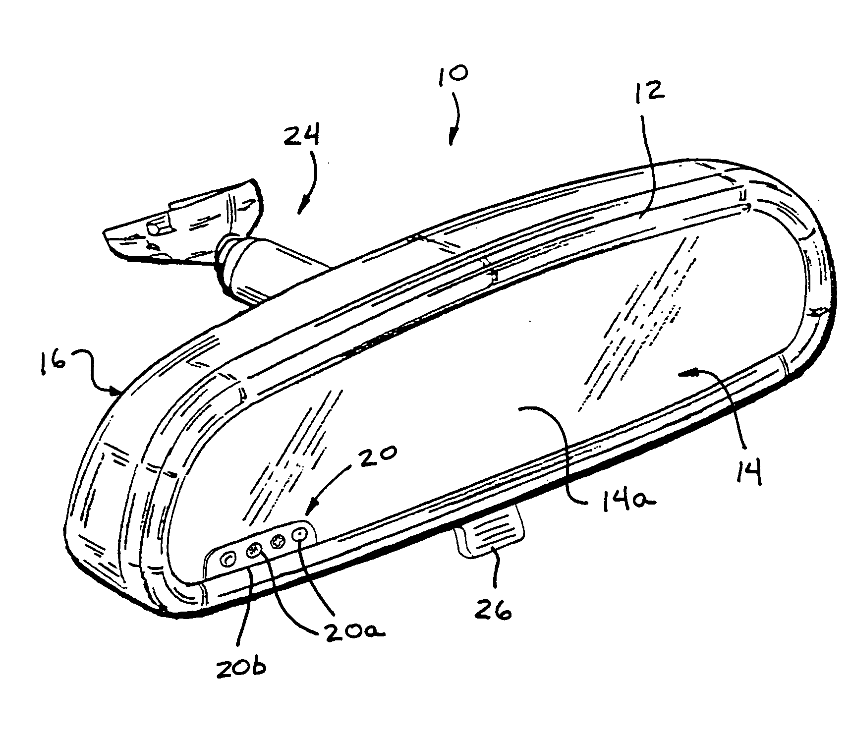
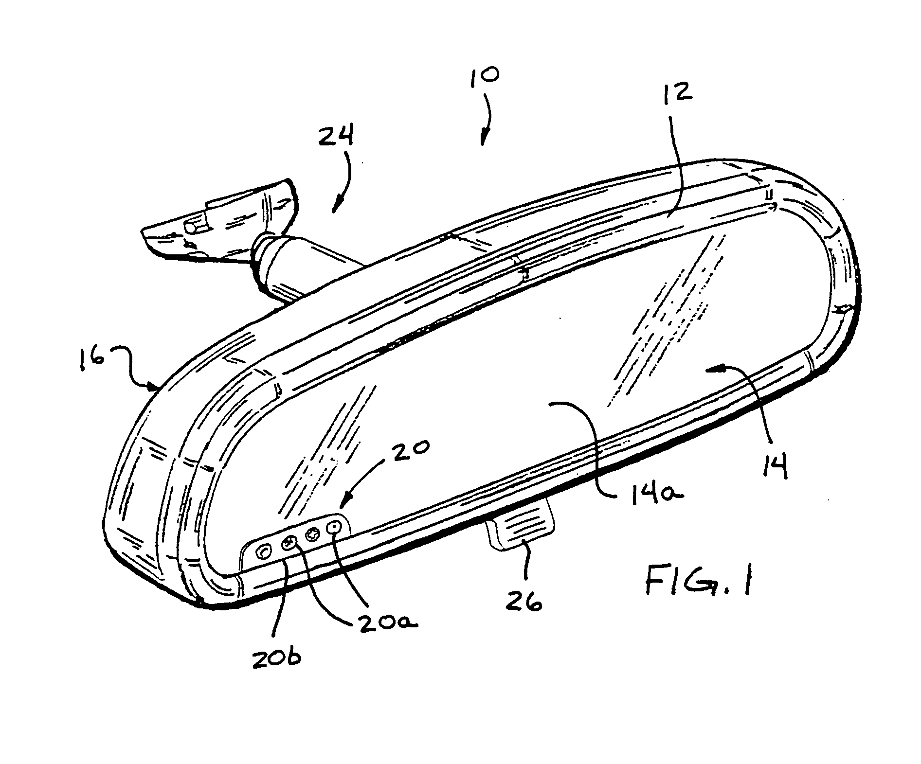
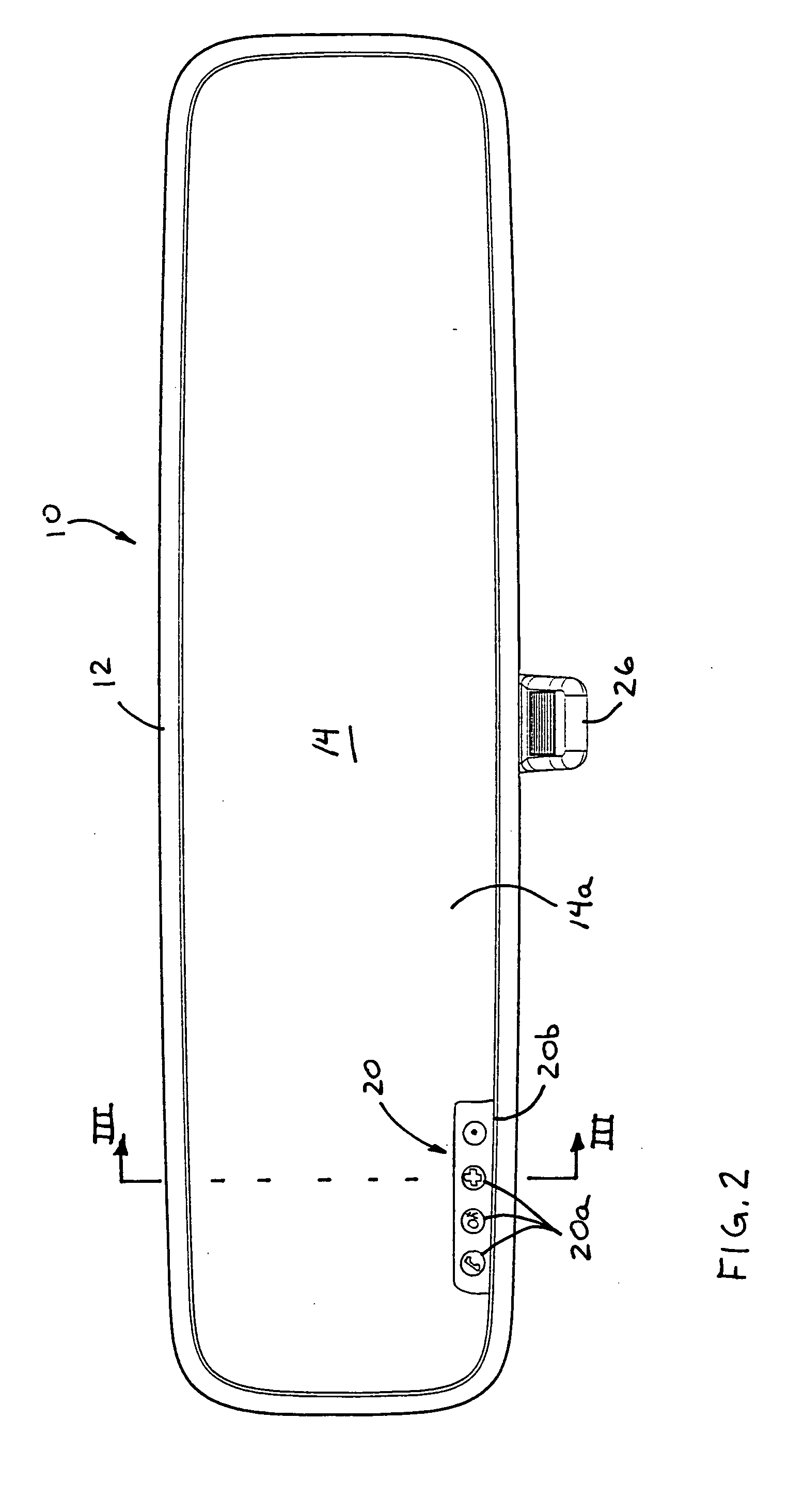
[0011] Therefore, the present invention provides an interior rearview mirror assembly which may include one or more overlay elements or membranes, which provide one or more user inputs or buttons or switches and / or one or more illumination sources and / or one or more displays or display elements. The overlay element may include circuitry. The overlay element or membrane is positioned on the viewable surface of the reflective element so that the user inputs / illumination sources / displays are readily viewable and / or accessible by a driver or occupant of the vehicle. The overlay element or membrane may be readily adhered or applied to the front surface of the reflective element and electronically connected to the appropriate circuitry (such as to a printed circuit board or to a flex circuit within the mirror assembly), such that the overlay element or membrane provides an efficient installation of such electronic features or accessories or inputs. The overlay element or membrane may be selected to provide a desired display or input option and thus may facilitate customization or personalization of the reflective element and mirror assembly, while the other components of the mirror assembly may comprise substantially universal or common or similar components. Importantly, because the user (such as the driver of the vehicle) is touching and pressing on membrane or touch sensors included as part of the overlay element or portion and is not touching the typically glass surface of the mirror reflective element, the problems associated with fingerprints, smears and the like on the glass front surface are avoided as the surface of the overlay element can be chosen to not readily show fingerprints, smears and the like by making that surface of the overlay to be diffusive, to be matte, to be colored and / or generally to have a surface finish that is not polished or not generally specularly reflective so as not to readily show fingerprints and the like.
[0012] Also, the overlay element and its accompanying ribbon connector (both are preferably thin, preferably having less than about 0.15 inches cross-sectional thickness, measured away from any dome membrane switch element; more preferably less than about 0.075 inches cross-sectional thickness preferably less than about 0.05 inches cross-sectional thickness) can be provided by a low-cost, membrane switch manufacturer, such as has been well established for provision of thin plastic membrane switches commonly found on appliances such as microwaves and calculators. The electrical conductors and any accompanying circuitry of the overlay element and its accompanying ribbon connector are sandwiched / disposed between plastic protective films or layers so as to be protected against the environmental elements, so as to be substantially moisture impervious, so as to be protected against physical wear and tear, and so as to be electrically insulated.

Problems solved by technology

Moreover, providing a touch-sensitive front surface for the mirror reflective element may involve specialized and potentially expensive surface coatings on the front surface of the mirror reflective element (for example, a transparent conductive coating such as indium tin oxide or doped tin oxide), which can add considerable cost to the manufacture of the mirror reflective element, and so requires a specialized mirror reflective element.

Method used


Image

  • Mirror assembly for vehicle
  • Mirror assembly for vehicle
  • Mirror assembly for vehicle

Examples


Embodiment Construction

[0028] Referring now to the drawings and the illustrative embodiments depicted therein, an interior rearview mirror assembly 10 for a vehicle includes a bezel portion 12, a mirror reflective element 14 positioned at and at least partially within the bezel portion, and a rear casing portion 16. Mirror assembly 10 may include a printed circuit board 18 (FIG. 3) or a flex circuit having an electronic accessory or circuitry thereon or integrated therein or attached thereto. Mirror assembly 10 includes a user input overlay element or membrane or sheet 20, which is positioned at or on the front surface 14a (the surface facing generally toward the driver of the vehicle when the mirror assembly is installed in the vehicle) and operable to activate / deactivate / control one or more accessories or displays or display elements or the like, as discussed below. The overlay element or membrane 20 may be adhered or bonded or otherwise attached or secured to the front surface 14a of the reflective ele...


PUM


Abstract

An interior rearview mirror assembly includes a reflective element having a front surface that is viewable by and directed generally toward a driver of a vehicle when the mirror assembly is installed in the vehicle. An overlay element applied to the front surface of the reflective element includes at least one user input for controlling at least one accessory or display of the mirror assembly or vehicle. An electrical connector connects the overlay element to circuitry at or within or associated with the mirror assembly. The overlay element may be applied to the reflective element at a desired location on the surface of the reflective element to provide a user input and / or a display at the front of the reflective element where it is readily viewable and accessible by a driver or occupant of the vehicle.

Description

CROSS REFERENCE TO RELATED APPLICATIONS [0001] The present application claims benefit of U.S. provisional applications, Ser. No. 60 / 575,904, filed Jun. 1, 2004 (Attorney Docket DON01 P-1157); and Ser. No. 60 / 624,320, filed Nov. 2, 2004 (Attorney Docket DON01 P-1185), which are hereby incorporated herein by reference in their entireties.FIELD OF THE INVENTION [0002] The present invention relates generally to the field of interior rearview mirror assemblies for vehicles and, more particularly, to interior rearview mirror assemblies which incorporate an accessory or feature, particularly an electronic accessory or feature. BACKGROUND OF THE INVENTION [0003] It is often desirable to provide an electronic feature in or at a vehicular interior rearview mirror assembly, such as a trainable garage door opener, a compass sensor and / or compass display, a tire pressure monitoring system receiver and / or display and / or the like, often along with the user inputs or buttons or switches associated ...

Claims


Application Information

Patent Timeline
Patent Type & Authority Applications(United States)
IPC IPC(8): B60R1/12G02B5/08
CPCB60R2001/1215B60R1/12
Inventor UKEN, JOHN T.LYNAM, NIALL R.
Owner DONNELLY CORP
Learn More