System and method for regulating resonant inverters

a technology of resonant inverters and system, applied in the direction of electric variable regulation, process and machine control, instruments, etc., can solve the problems of high sensitivity near resonance and strong dependence on resonant, and achieve the effect of rapid design cycles

Inactive Publication Date: 2005-12-01
GENERAL ELECTRIC CO
View PDF13 Cites 40 Cited by
  • Summary
  • Abstract
  • Description
  • Claims
  • Application Information

AI Technical Summary

Benefits of technology

[0006] It is therefore desirable to provide for direct digital phase control of resonant inverters that achieves the benefits of te

Problems solved by technology

However, direct frequency control results in a number of disadvantages, including high sensitivity near resonance, strong dependence on resonant tank compo

Method used


Image

  • System and method for regulating resonant inverters
  • System and method for regulating resonant inverters
  • System and method for regulating resonant inverters

Examples


Embodiment Construction

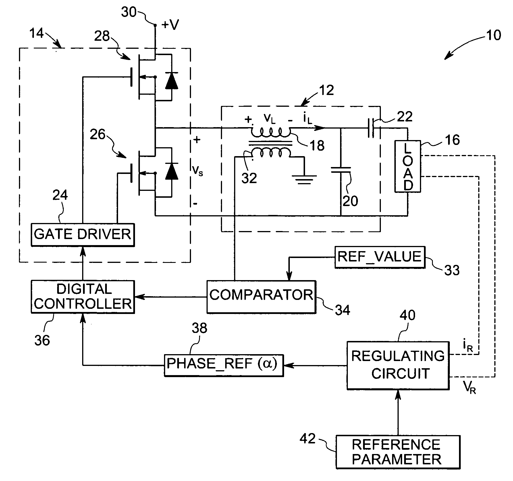
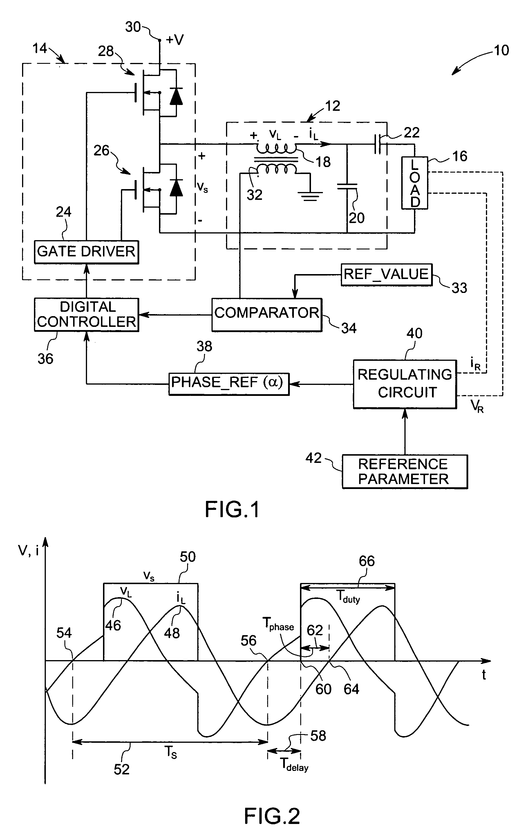
[0016] Referring now to FIG. 1, an exemplary resonant inverter system 10 includes a resonant tank 12, a switching circuit 14 and a load 16. In the illustrated figure, the resonant tank 12 is generally shown as an LCC resonant tank circuit comprising of a resonant inductor 18 and two discrete resonant capacitors 20 and 22. As would be appreciated by those skilled in the art, the resonant tank 12 may comprise of any alternative topologies. In this exemplary embodiment, a half bridge switching inverter circuit 14 is used, that converts the dc (direct current) voltage to a square-wave ac (alternating current) output. The half bridge switching inverter circuit further includes a gate driver 24, two discrete power MOSFETs 26 and 28. Alternatively, FETs, IGBTs, BJTs, or any other suitable switching devices may be used to design the half bridge switching inverter circuit 14. As would be appreciated by one skilled in the art other switching circuits can also be used without deviating from th...


PUM


Abstract

A technique is provided for direct digital phase control of resonant inverters based on sensing of one or more parameters of the resonant inverter. The resonant inverter control system includes a switching circuit for applying power signals to the resonant inverter and a sensor for sensing one or more parameters of the resonant inverter. The one or more parameters are representative of a phase angle. The resonant inverter control system also includes a comparator for comparing the one or more parameters to a reference value and a digital controller for determining timing of the one or more parameters and for regulating operation of the switching circuit based upon the timing of the one or more parameters.

Description

STATEMENT REGARDING FEDERALLY SPONSORED RESEARCH & DEVELOPMENT [0001] This invention was made with Government support under contract number DE-FC26-02NT41252 awarded by U.S. Department of Energy. The Government has certain rights in the invention.BACKGROUND [0002] The invention relates generally to the field of digital phase controllers, and more specifically to the field of direct digital phase control for resonant inverters, such, as for providing power to a lamp assembly. [0003] High frequency resonant inverters are used in a wide range of applications requiring high quality ac output, including electronic ballasts for lighting, induction-based heating appliances, medical equipment, and semiconductor processing equipment. In most applications, a closed-loop controller is required to regulate the output waveforms for improved rejection of component tolerances and variations in environmental conditions. Common approaches for regulating the output include control of the input dc bus...

Claims


Application Information

Patent Timeline
IPC IPC(8): H02M3/156H02M7/537
CPCY02B70/1425H02M3/156Y02B70/10
Inventor STEVANOVIC, LJUBISA DRAGOLJUBZANE, REGAN ANDREW
Owner GENERAL ELECTRIC CO
Why Eureka
Try Eureka