Wireless transmission method and wireless transmitter having a plurality of antennas

Inactive Publication Date: 2005-12-01
KK TOSHIBA
View PDF4 Cites 30 Cited by
  • Summary
  • Abstract
  • Description
  • Claims
  • Application Information

AI Technical Summary

Benefits of technology

[0009] It is an object of the present invention to provide a wireless transmission method and wireles

Problems solved by technology

Recently, the wireless communication systems are in a tendency toward increase of complexity.
In the wireless communication system thus requiring a high immediateness at the reception end, when transmission is done at the trans

Method used


Image

  • Wireless transmission method and wireless transmitter having a plurality of antennas
  • Wireless transmission method and wireless transmitter having a plurality of antennas
  • Wireless transmission method and wireless transmitter having a plurality of antennas

Examples


Example

First Embodiment

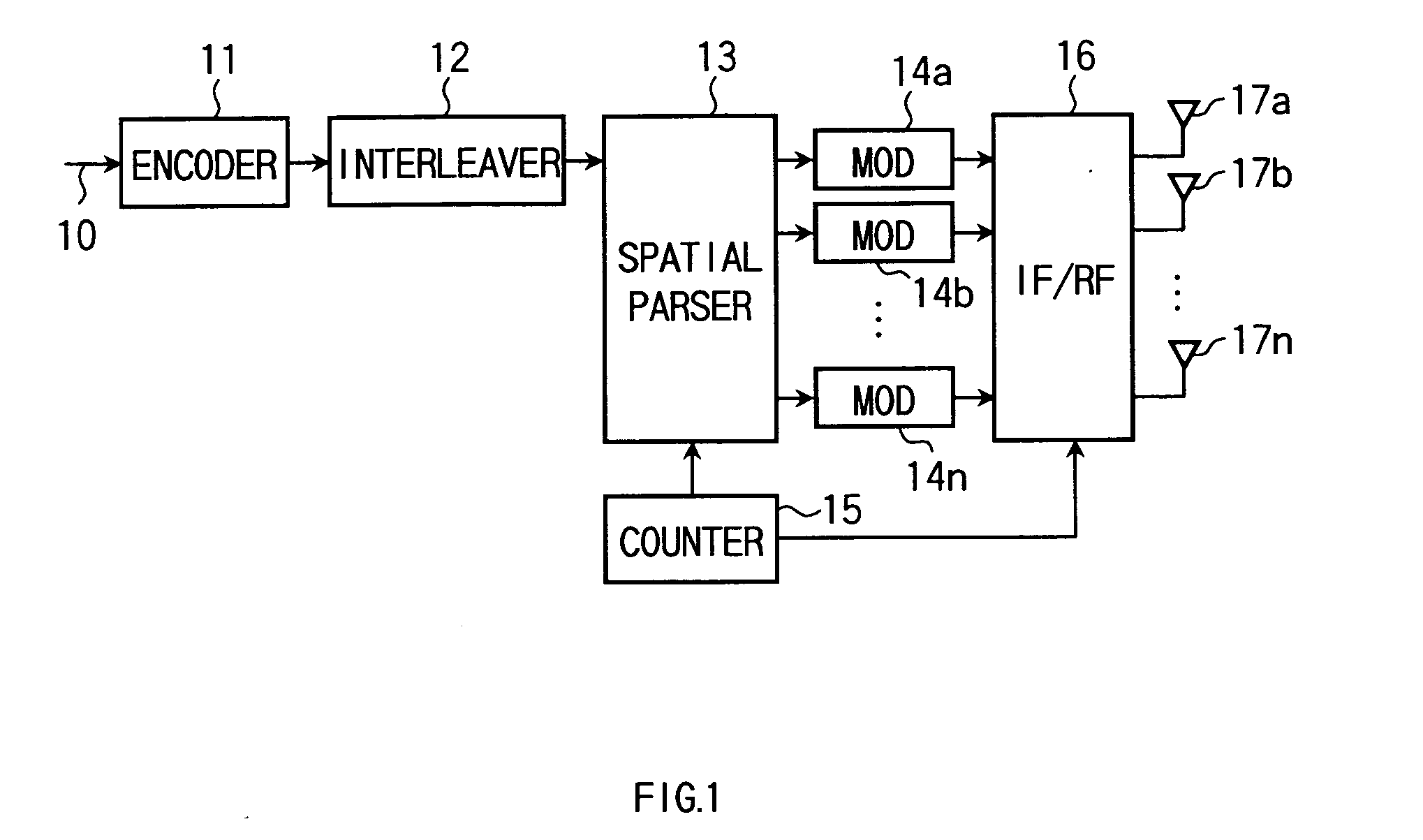
[0029] Referring to FIG. 1, description is made on a transmitter according to a first embodiment of the invention. FIG. 1 is a physical layer in the transmitter to which data to be transmitted (bit string) 10 is inputted per the transmission unit (e.g. frame or packet) from the higher layer. For example, for a wireless LAN, the data 10 is allocated first with a known signal for channel estimation and AGC (automatic gain control) and then with a data signal, in each transmission unit thereof. The inputted data 10 is subjected to error-correction coding by an encoder 11 and further interleave processing by an interleaver 12, followed by being inputted to a spatial parser 13.

[0030] The spatial parser 13 divides the input data into a plurality of streams in the same number as the transmission antennas according to an instruction from a counter 15, or outputs it as one stream without division. Where the spatial parser 13 divides the input data into a plurality of stream...

Example

Second Embodiment

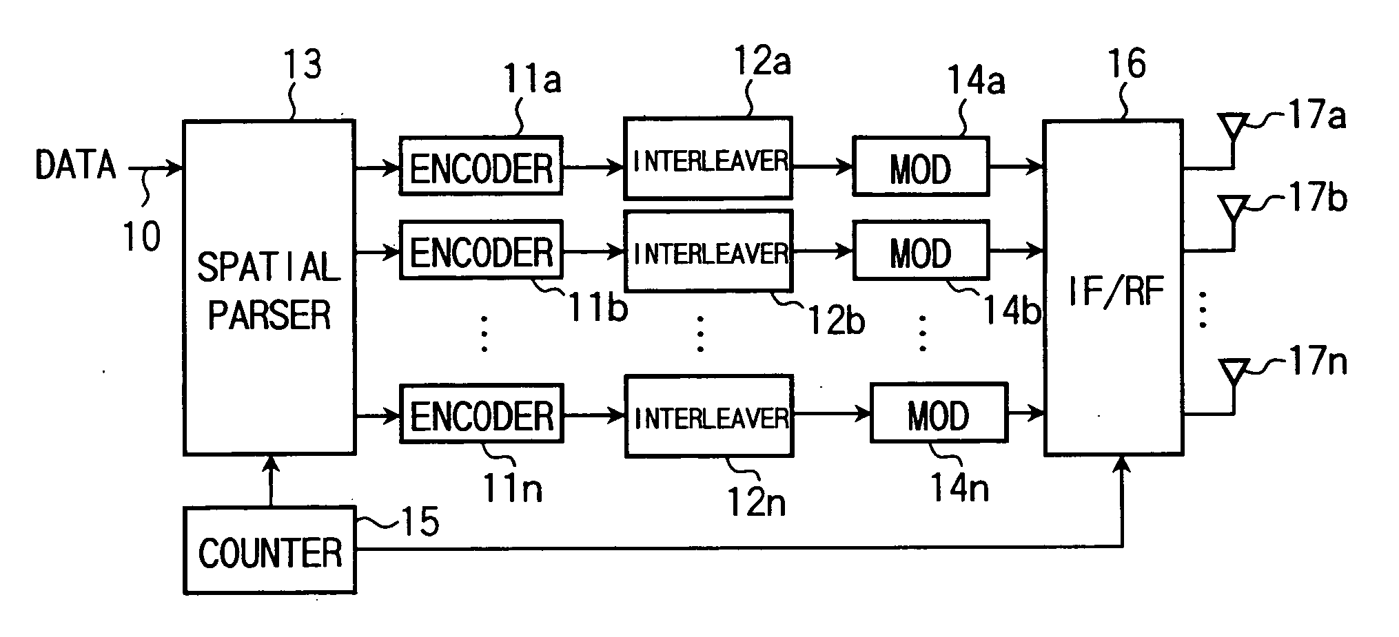
[0047]FIG. 5 shows a transmitter in a second embodiment as a modification to the transmitter in the first embodiment of the invention. The data to be transmitted 10, before being encoded, is divided by a spatial parser 13 into streams and then subjected to encode and interleave, stream by stream, by encoders 11a, 11b, . . . , 11n and interleavers 12a, 12b, 12n. The data, after encode and interleave processed, is inputted to the modulators 14a, 14b, . . . , 14n. The processing at the modulators 14a, 14b, . . . , 14n and the subsequent is similar to that of the first embodiment, hence omitting of explanations.

[0048] The spatial parser 13 makes a processing similarly to the first embodiment, excepting in that there is an input of pre-encode data. Consequently, the second embodiment can enjoy the effect similarly to the first embodiment. In the second embodiment, the receiver is satisfactorily similar to that of the first embodiment.

Example

Third Embodiment

[0049] In a transmitter according to a third embodiment of the invention, there are inserted CDD (cyclic delay diversity) processors 18a, 18b, . . . , 18n and switches 19a, 19b, . . . , 19n between the modulators 14a, 14b, . . . , 14n and the IF / RF stage 16 as shown in FIG. 6, in the transmitter of FIG. 1. The switches 19a, 19b, . . . , 19n are controlled according to an instruction from the counter 15, to select any of an output of the modulator 14a, 14b, . . . , 14n and an output of the CDD processors 18a, 18b, . . . , 18n.

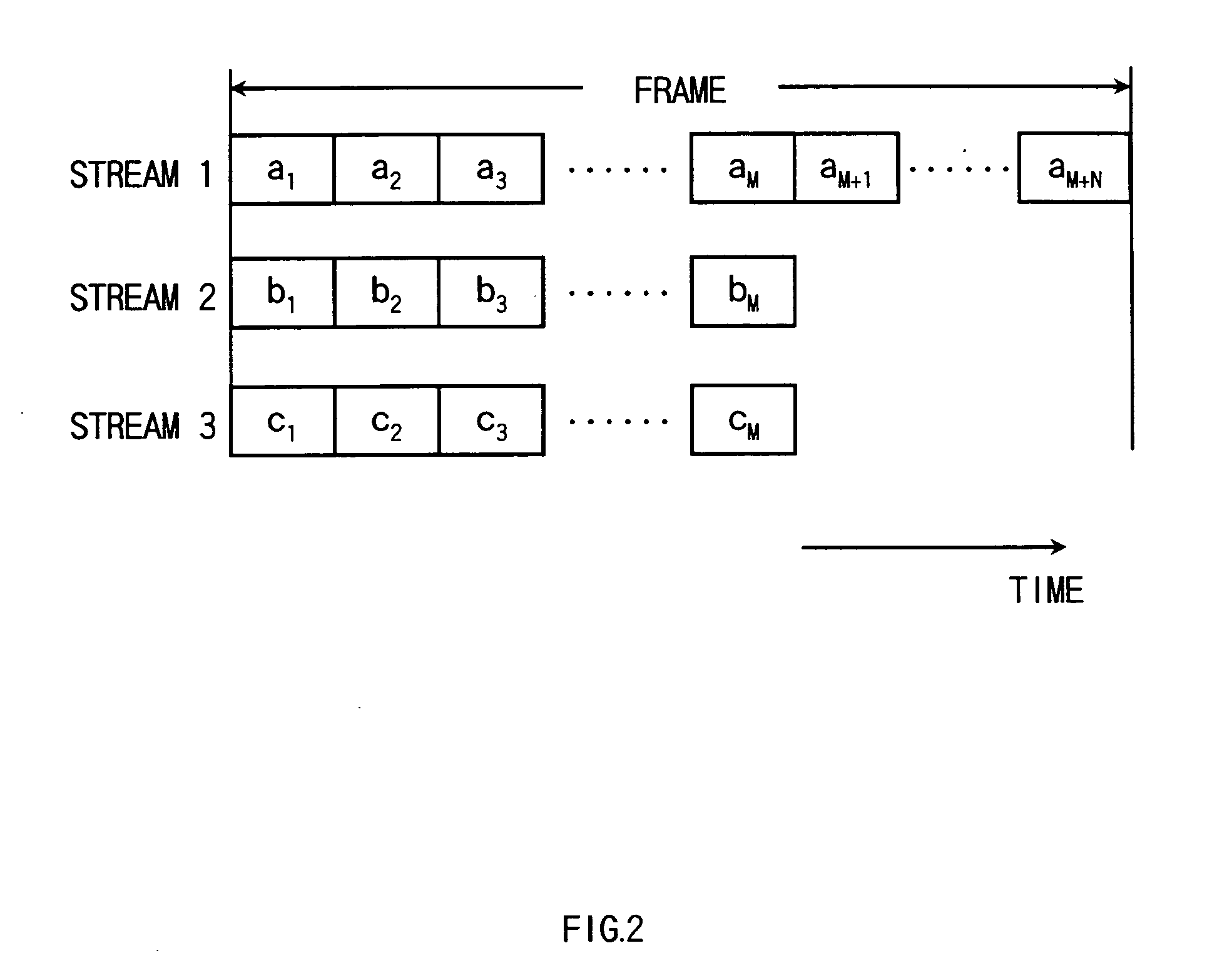
[0050] Using FIGS. 7 and 8, description is made on the operation of the transmitter of FIG. 6. The operation is similar to that of the first embodiment except for the CDD processors 18a, 18b, . . . , 18n and the switches 19a, 19b, . . . , 19n. Namely, provided that the number of symbols is M+N (M and N are integers equal to or greater than 1) in the transmission unit of the data 10, the spatial parser 13 performs a stream demultiplexing operati...


PUM


Abstract

In a wireless transmission method and wireless transmitter using a plurality of antennas at least in signal transmission, a process requiring a high immediateness is enabled to implement at the reception end. A wireless communication apparatus, for making a transmission based on a transmission unit being specified as a predetermined plurality of symbols, sends a plurality of symbols other than the last N symbols (N is an integer equal to or greater than 1) of the transmission unit through use of a plurality of antenna, and the last N symbols of the transmission unit through use of one antenna.

Description

CROSS-REFERENCE TO RELATED APPLICATIONS [0001] This application is based upon and claims the benefit of priority from the prior Japanese Patent Application No. 2004-158335, filed May 27, 2004, the entire contents of which are incorporated herein by reference. BACKGROUND OF THE INVENTION [0002] 1. Field of the Invention [0003] This invention relates to a wireless transmission method with a wireless transmitter using a plurality of antennas. [0004] 2. Description of the Related Art [0005] There are many proposals of wireless communication systems having a plurality of antennas for use in sending signals. Particularly, the wireless communication system, using a plurality of antennas at the transmission end besides at the reception end, is called MIMO (multi-input multi-output). [0006] Such wireless communication systems include a spatial-multiplexing scheme for sending independent, different pieces of information on a stream-by-stream basis (stream: information sequence sent at each an...

Claims


Application Information

Patent Timeline
IPC IPC(8): H04J99/00H04B7/04H04B7/06H04B7/08H04B7/26H04L1/06
CPCH04B7/0669H04B7/0671H04B7/0691H04B7/0697H04L1/06H04B7/0868H04B7/0891H04B7/0894H04B7/0822
Inventor TAKEDA, DAISUKETAKAGI, MASAHIROAOKI, TSUGUHIDETANABE, YASUHIKODEGUCHI, NORITAKA
Owner KK TOSHIBA
Why Eureka
Try Eureka