

Sterilization/disinfection cycle control
a technology of disinfection cycle and sterilization, applied in disinfection, chemical methods analysis, instruments, etc., can solve the problems of inflexibility in controlling such machines, and achieve the effect of removing residual sterilan
- Summary
- Abstract
- Description
- Claims
- Application Information
AI Technical Summary
Benefits of technology
Problems solved by technology
Method used
Image

Examples
Embodiment Construction
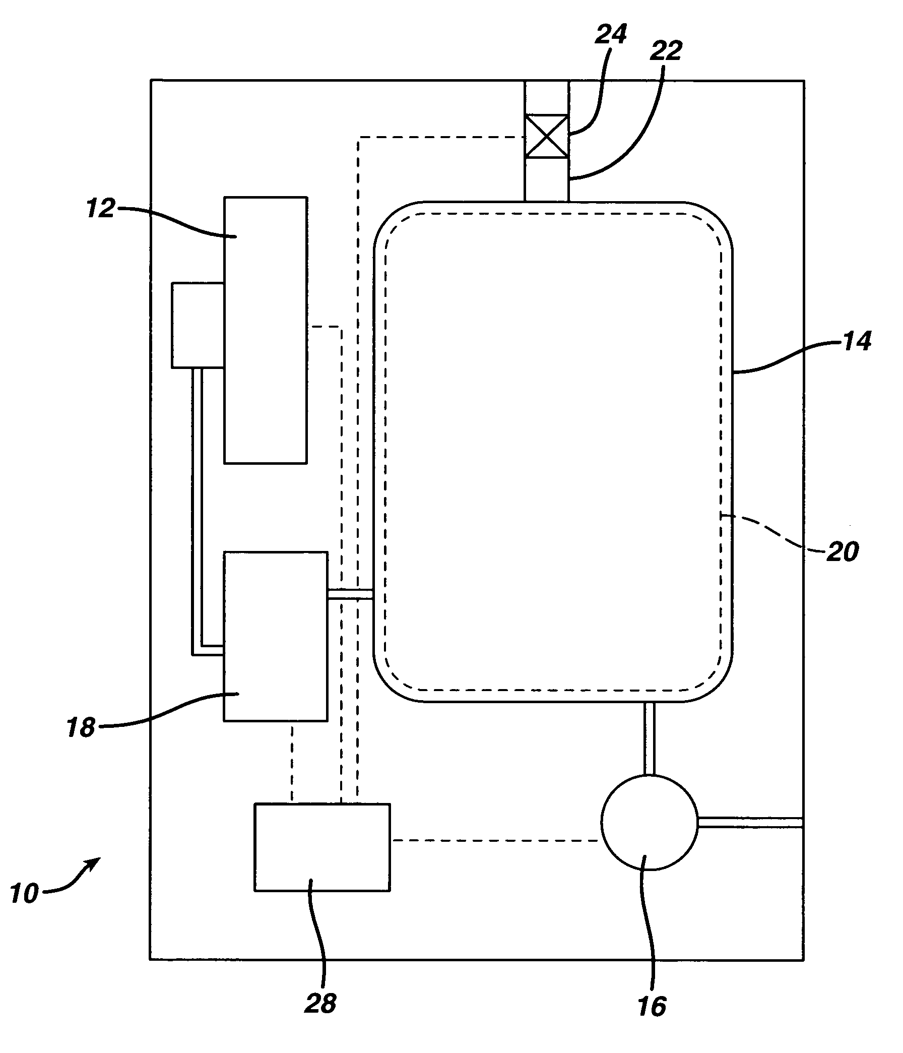
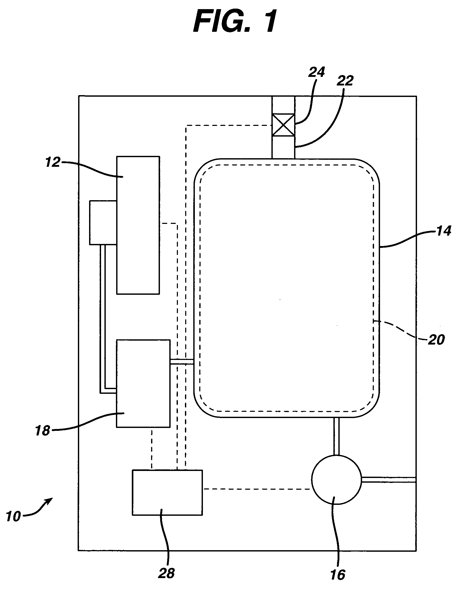
[0033] Sterilizer Overall Configuration
[0034]FIG. 1 shows in block diagram form a vapor phase sterilizer 10 employing a cassette handling system 12 according to the present invention. The sterilizer 10 comprises a vacuum chamber 14 and a vacuum pump 16 for exhausting atmosphere therefrom. A vaporizer 18 receives liquid sterilant from the cassette handling system 12 and supplies it in vapor form to the vacuum chamber 14. A screen grid electrode 20 is provided within the vacuum chamber 14 for exciting the contents into the plasma phase during a portion of the sterilization cycle. A micro filtered vent 22 and valve 24 allow sterile air to enter the vacuum chamber 14 and break the vacuum therein. A control system 28 ties in to all of the major components, sensors and the like within the sterilizer 10 to control the sterilization cycle.
[0035] A typical sterilization cycle might include drawing a vacuum upon the vacuum chamber 14 and turning on power to the electrode 20 to evaporate and...
PUM
| Property | Measurement | Unit |
|---|---|---|
| lumen length | aaaaa | aaaaa |
| length | aaaaa | aaaaa |
| internal diameter | aaaaa | aaaaa |
Abstract
Description
Claims
Application Information