Fuel cell separator, fuel cell device, and electronic applied device

a technology of electronic applied devices and fuel cells, which is applied in the direction of cell components, electrochemical generators, cell component details, etc., can solve the problems of reducing the size of the fuel cell device itself, affecting the operation of the electronic equipment to be driven, and limiting the layout of the fuel cell body, so as to achieve the effect of reducing the size of the electronic applied devi

a technology of electronic applied devices and fuel cells, which is applied in the direction of cell components, electrochemical generators, cell component details, etc., can solve the problems of reducing the size of the fuel cell device itself, affecting the operation of the electronic equipment to be driven, and limiting the layout of the fuel cell body, so as to achieve the effect of reducing the size of the electronic applied devi

US20050266295A1Inactive Publication Date: 2005-12-01SONY CORP

Image

  • Fuel cell separator, fuel cell device, and electronic applied device
  • Fuel cell separator, fuel cell device, and electronic applied device
  • Fuel cell separator, fuel cell device, and electronic applied device

Examples


Embodiment Construction

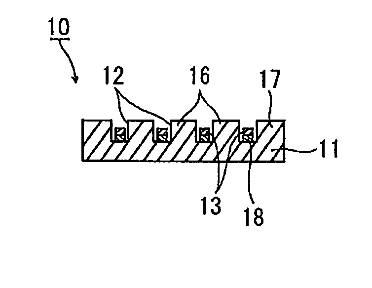
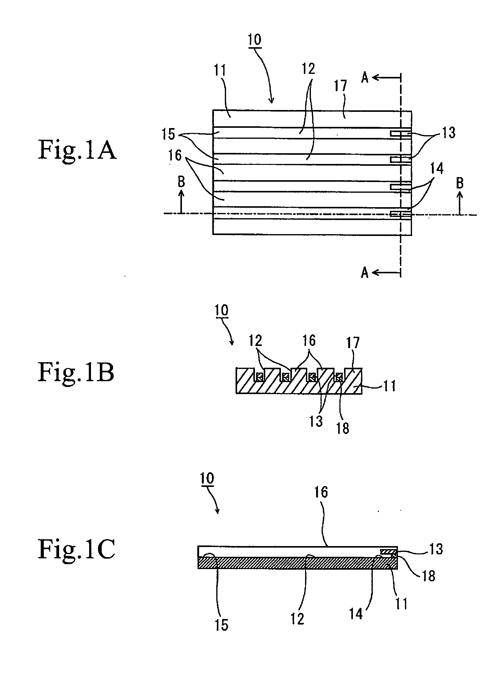
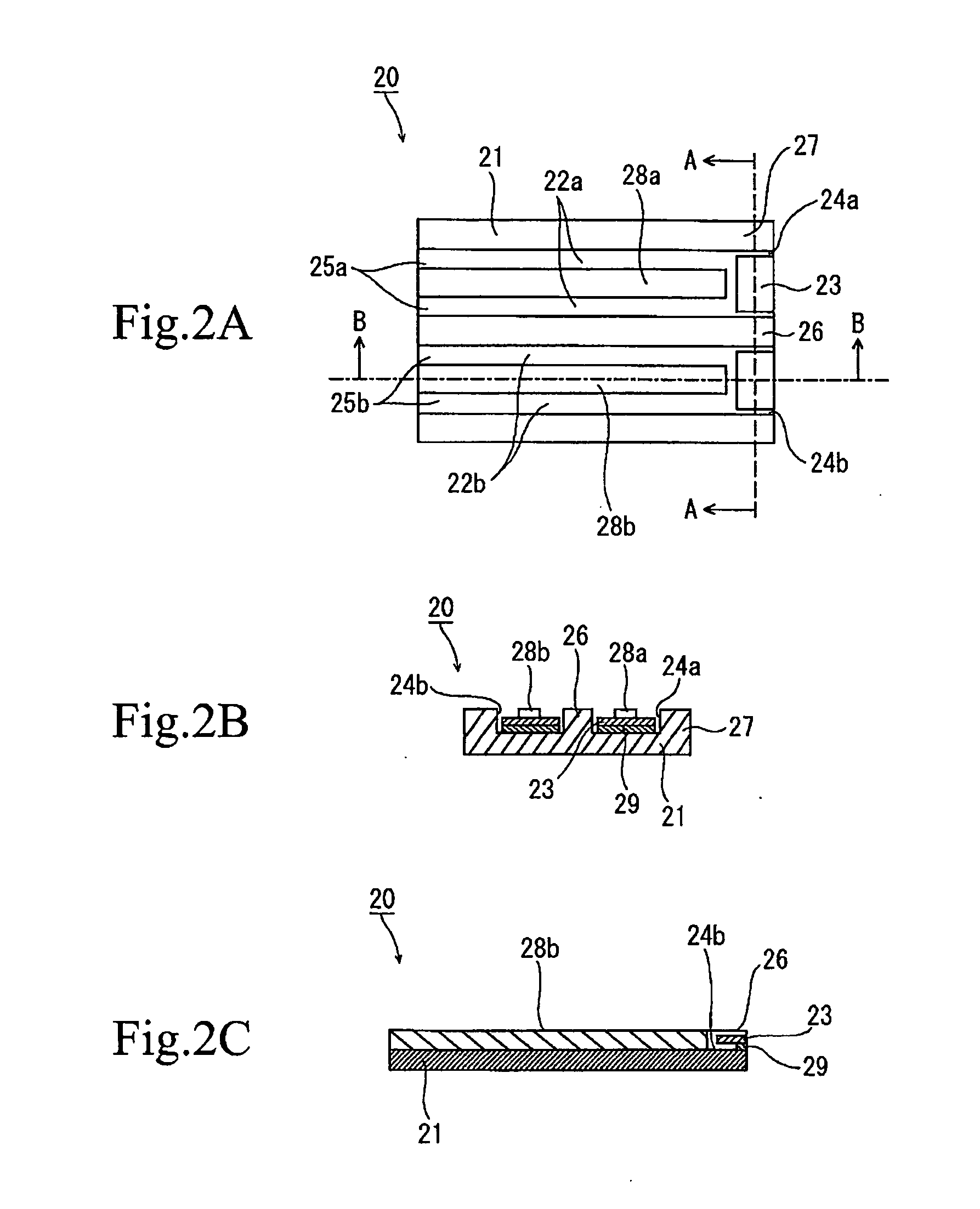
[0036] The fuel cell separator, the fuel cell device, and the electronic applied device according to the present invention will now be described in more detail with reference to the drawings. The fuel cell separator according to the present invention has a separator body adapted to come into contact with a platelike generating element such as an MEA, thereby constituting a generating cell. The fuel cell separator is adapted to be provided on the oxygen electrode side of the generating element, and is formed with a channel for supplying oxygen as a fluid oxidant to the generating element. Air containing the oxygen is supplied from the outside of the generating cell to the channel. Further, a fuel such as hydrogen gas or methanol is supplied to the fuel electrode side of the generating element. Then, the generating element performs electric power generation by using the oxygen as the fluid oxidant and the fuel. The fuel cell separator according to the present invention further has flu...


PUM

PropertyMeasurementUnit
electrical continuityaaaaaaaaaa
piezoelectricaaaaaaaaaa
shape memoryaaaaaaaaaa

Abstract

Fuel cell separation, fuel cell device, and electronic applied device technical field are provided. A fuel cell separator capable of making a fuel cell device compact and reducing variations in air supply amount to generating cells. Oscillating fans as fluid oxidant supplying means are respectively provided at openings of channels. The oscillating fans are individually driven to respectively supply air into the channels. The oscillating fans are included in a separator body of a separator. As compared with the case that the oscillating fans are provided separately from a fuel cell body having the separator as a component, the limitation to layout of the fuel cell body and various units for effecting stable electric power generation in the fuel cell body can be reduced, and the fuel cell device can be reduced in size.

Description

TECHNICAL FIELD [0001] The present invention relates to a fuel cell separator, fuel cell device, and electronic applied device, and more particularly to a fuel cell separator, fuel cell device, and electronic applied device wherein the fuel cell device can be reduced in size with almost no limitation to layout of a fuel cell body in the fuel cell device, and air can be smoothly supplied to each generating cell. BACKGROUND ART [0002] A fuel cell is a power generating device including a generating cell for performing electric power generation by the electrochemical reaction of a fluid fuel such as hydrogen gas or methanol and a fluid oxidant such as oxygen contained in air. In the case of a solid polymer type fuel cell, it generally has a structure formed by sandwiching a proton conductor membrane between an oxygen electrode and a fuel electrode. The oxygen electrode is supplied with air containing oxygen, and the fuel electrode is supplied with a fluid fuel. In performing electric po...

Claims


Application Information

Patent Timeline
01 Dec 2005
Publication
US20050266295A1
IPC
H01M8/04; H01M8/06; H01M8/02; H01M8/10; H01M8/24
CPC
H01M8/0247; H01M8/0258; Y02E60/50; H01M8/241; H01M8/04089; H01M8/2457
Inventors
TAKAI, YUICHI