Moisture transport system for contact electrocoagulation

a technology of moisture transport and electrocoagulation, which is applied in the direction of prosthesis, contraceptive devices, applications, etc., can solve the problems of ineffective heating process, inability to account for factors, and inability to achieve the ablation depth and ablation profile of such devices by assumption

Inactive Publication Date: 2005-12-01
CYTYC CORP
View PDF20 Cites 77 Cited by
  • Summary
  • Abstract
  • Description
  • Claims
  • Application Information

AI Technical Summary

Problems solved by technology

However, because no data or feedback is available to guide the physician as to how deep the tissue ablation has progressed, controlling the ablation depth and ablation profile with such devices can only be done by assumption.
For example, the heated fluid method is a very passive and ineffective heating process which relies on the heat conductivity of the tissue.
This process does not account for variations in factors such as the amount of contact between the balloon and the underlying tissue, or cooling effects such as those of blood circulating through the organ.
RF ablation techniques can achieve more effective ablation since it relies on active heating of the tissue using RF energy, but presently the depth of ablation using RF techniques can only be estimated by the physician since no feedback can be provided as to actual ablation depth.
Because ablation is carried out within a closed cavity within the body, the steam cannot escape and may instead force itself deeply into the tissue, or it may pass into areas adjacent to the area intended to be ablated, causing embolism or unintended burning.
Another problem with prior art ablation devices is that it is difficult for a physician to find out when ablation has been carried out to a desired depth within the tissue.
Thus, it is often the case that too much or too little tissue may be ablated during an ablation procedure.

Method used


Image

  • Moisture transport system for contact electrocoagulation
  • Moisture transport system for contact electrocoagulation
  • Moisture transport system for contact electrocoagulation

Examples


first exemplary embodiment

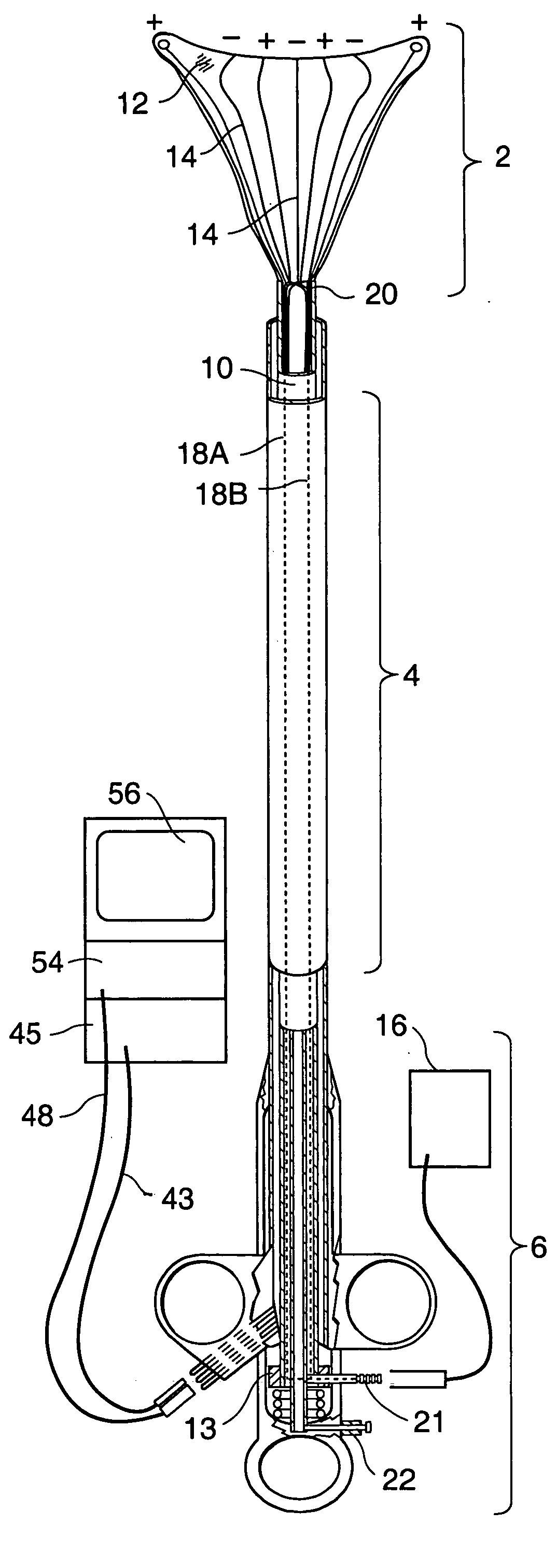
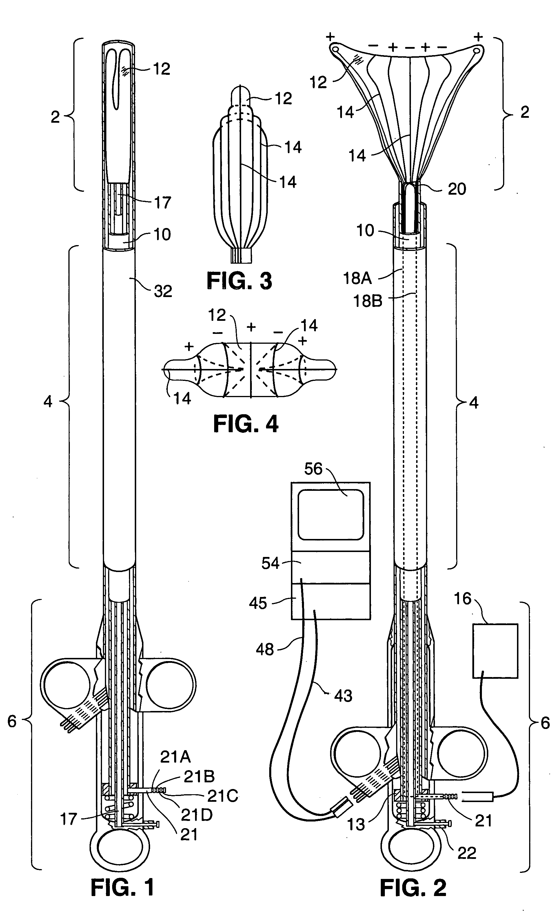
[0086] Operation of the first exemplary embodiment of an ablation device according to the present invention will next be described.

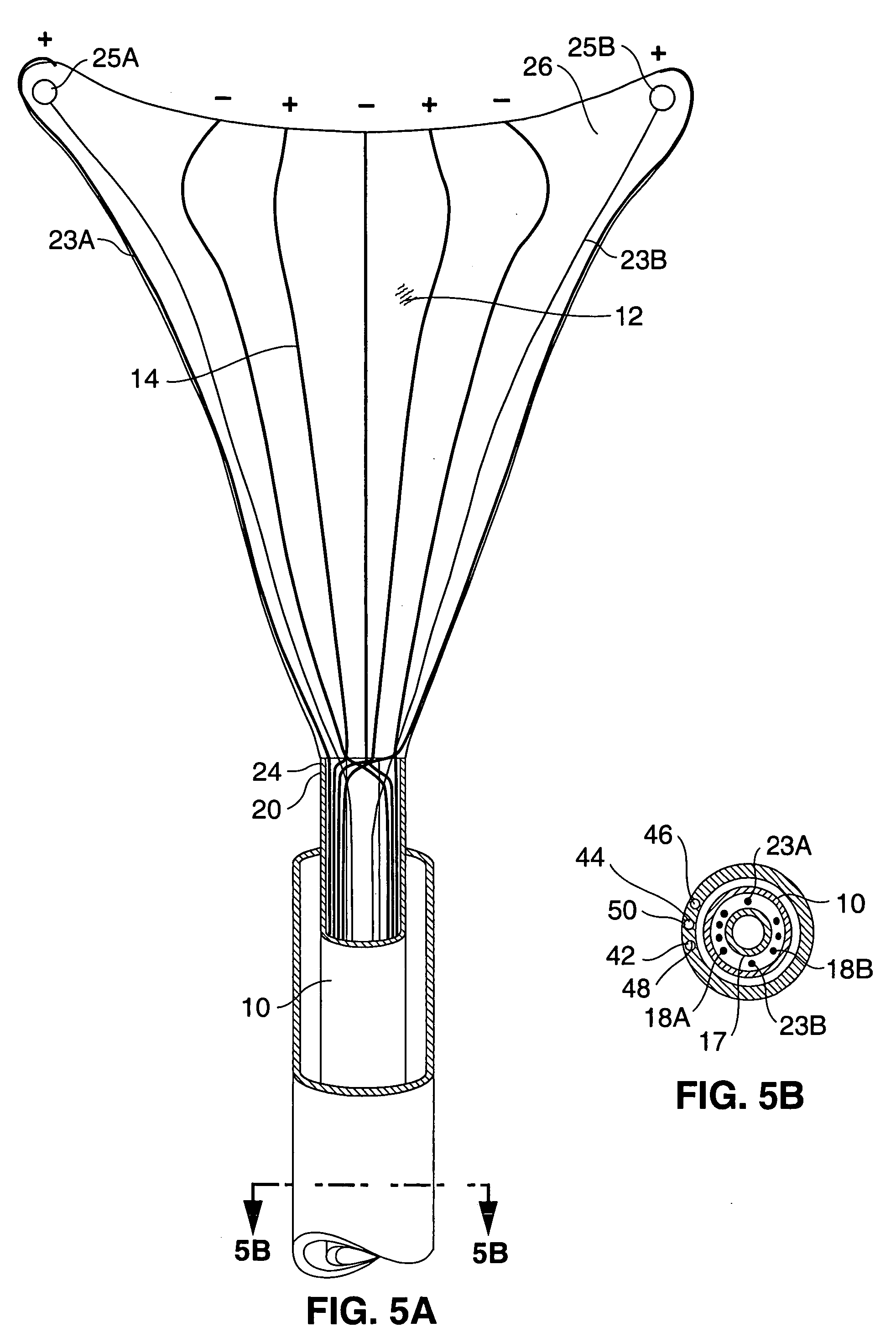
[0087] Referring to FIG. 1, the device is initially configured for use by positioning the introducer sheath 32 distally along the shaft 10, such that it compresses the electrode carrying means 12 within its walls.

[0088] At this time, the electrical connector 21 is connected to the RF generator 16, and the fiberoptic cable 48 and the illumination cable 50 are connected to the illumination source, monitor, and camera, 54, 56, 45. The suction / insufflation unit 40 is attached to suction / insufflation port 38 on the handle rail 35. The suction / insufflation unit 40 is preferably set to deliver carbon dioxide at an insufflation pressure of 20-200 mmHg.

[0089] Next, the distal end of the apparatus is inserted through the vaginal opening V and into the uterus U as shown in FIG. 6, until the distal end of the introducer sheath 32 contacts the fundus F of the uter...

second exemplary embodiment

[0155] In preparation for ablating the uterus utilizing the second exemplary embodiment, the user measures the uterine length using a uterine sound device. The user next positions sliding collar 184 (FIG. 32B) adjacent to calibration marks 182 corresponding to the measured uterine length (e.g. 4.5 cm) and rotates the collar section 186 to engage its internally positioned teeth with the rack 180. This locks the longitudinal position of the heel 188 (FIG. 32A) such that it will engage with the spring member 190 when the array has been exposed to the length set by the sliding collar.

[0156] Next, with the grips 142, 144 in their resting positions to keep the applicator head 102 covered by sheath 104, the distal end of the device 100 is inserted into the uterus. Once the distal end of the sheath 104 is within the uterus, grips 142, 144 are squeezed together to deploy the applicator head 102 from sheath 104. Grips 142, 144 are squeezed until heel 188 engages with locking spring member 19...


PUM


Abstract

An apparatus and method for use in performing ablation or coagulation of organs and other tissue includes a metallized fabric electrode array which is substantially absorbent and / or permeable to moisture and gases such as steam and conformable to the body cavity. The array includes conductive regions separated by insulated regions arranged to produce ablation to a predetermined depth. Following placement of the ablation device into contact with the tissue to be ablated, in RF generator is used to deliver RF energy to the conductive regions and to thereby induce current flow from the electrodes to tissue to be ablated. As the current heats the tissue, moisture (such as steam or liquid) leaves the tissue causing the tissue to dehydrate. Suction may be applied to facilitate moisture removal. The moisture permeability and / or absorbency of the electrode carrying member allows the moisture to leave the ablation site so as to prevent the moisture from providing a path of conductivity for the current.

Description

RELATED APPLICATIONS [0001] This application claims the benefit of U.S. Provisional Application No. 60 / 084,791, filed May 8, 1998, and is a Continuation in Part of copending U.S. application Ser. No. 08 / 632,516, filed Apr. 12, 1996, now U.S. Pat. No. 5,769,880, issued Jun. 23, 1998.FIELD OF THE INVENTION [0002] The present invention relates generally to the field of apparatuses and methods for ablating or coagulating the interior surfaces of body organs. Specifically, it relates to an apparatus and method for ablating the interior linings of body organs such as the uterus and gallbladder. BACKGROUND OF THE INVENTION [0003] Ablation of the interior lining of a body organ is a procedure which involves heating the organ lining to temperatures which destroy the cells of the lining or coagulate tissue proteins for hemostasis. Such a procedure may be performed as a treatment to one of many conditions, such as chronic bleeding of the endometrial layer of the uterus or abnormalities of the ...

Claims


Application Information

Patent Timeline
Patent Type & Authority Applications(United States)
IPC IPC(8): A61B17/22A61B17/42A61B18/14A61M1/00A61M16/04
CPCA61B18/1485A61B2019/4009A61B2017/4216A61B2018/00291A61B2018/126A61B2019/465A61B17/42A61B18/18A61M16/0481A61B18/1482A61B19/40A61B2018/00559A61B2018/00577A61B2018/00708A61B2017/22051A61B90/04A61B2090/0409A61B2090/065A61M16/0463A61M16/0427A61B18/14
Inventor TRUCKAI, CSABASAMPSON, RUSSEL MAHLONSQUARCIA, STEPHANIERAMIREZ, ALFONSO LAWRENCEHILARIO, ESTELA
Owner CYTYC CORP
Why Eureka
Try Eureka