Devices, systems and methods for tissue repair

Inactive Publication Date: 2005-12-01
BAY INNOVATION GROUP
View PDF21 Cites 176 Cited by
  • Summary
  • Abstract
  • Description
  • Claims
  • Application Information

AI Technical Summary

Benefits of technology

[0023] In yet another exemplary embodiment, the present invention is a method for arthroscopic plication of an interior concave surface of a capsular structure. T

Problems solved by technology

Such instability may include, for example, intentional or accidental tears, cuts, stretching, loosening, deterioration of structure, loss of firmness, and the like.
No matter what type of instability is present or whether the tissue to be repaired is classified as orthopedic or non-orthopedic, similar issues and objectives are encountered by the surgeon, namely, creating a stable and reliable structure and doing so in as easy and reliable manner as possible.
For example, certain joints, such as hips, knees, shoulders and elbows contain tissues that are common sources of problems, whether natural or induced, that require extensive physical therapy or surgery to correct.
Of such tissues or tissue structures, a common source of medical problems occurs in the joints.
Joint instability is a complex clinical problem associated with a variety of treatment options that include the use of arthroscopic and open surgical methods.
However, adequate arthroscopic methods that approximate the clinical outcome achieved by open surgical methods for reducing excessive joint laxity have been slow to develop or have begun to show less than optimal long term clinical outcomes (e.g., thermal methods).
The shoulder joint, in particular, has inherent instability because of its large range and motion combined with the relatively shallow joint bony socket (glenoid).
Damage to or laxity of one of these stabilizing structures can result in the presentation of clinically relevant shoulder instability.
Most typically, the instability of the shoulder stems from disruption and/or looseness (excessive capsule laxity) of the shoulder capsule.
The resulting subluxation or dislocation of the joint can be painful and debilitating for the individual.
A loose shoulder capsule may be tightened readily when a standard open incision is used, but tightening the shoulder capsule arthroscopically poses significa

Method used


Image

  • Devices, systems and methods for tissue repair
  • Devices, systems and methods for tissue repair
  • Devices, systems and methods for tissue repair

Examples


example a

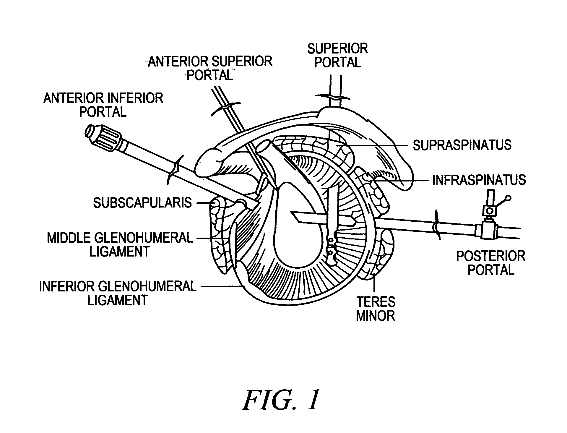
[0192] Arthroscopic repair of Bankart lesion with arthroscopic suture plication of associated anterior capsular laxity.

[0193] Following examination under anesthesia and standard surgical prepping and draping, standard anterior and posterior glenohumeral arthroscopy portal are established. The patient may be positioned either in the lateral decubitus position or in a beach chair position. Following completion of diagnostic arthroscopy, attention is first focused on repair of the Bankart lesion. After the Bankart repair has been performed, residual anterior capsular laxity is assessed. The surgeon subsequently places the humerus in the desired position (in terms of external rotation and abduction; this will vary according to patient demand and individual surgeon preference). With the shoulder placed in the desired position, capsular redundancy is addressed via performing a suture plication. The capsular plication deployment device is introduced through a standard anterosuperior porta...

example b

[0194] Capsular laxity without an associated Bankart lesion (e.g., anterior unidirectional atraumatic instability).

[0195] Following examination under anesthesia, standard anterior and posterior glenohumeral arthroscopic portals are established. A thorough diagnostic glenohumeral arthroscopy is performed with specific attention to determining the extent and distribution of capsular laxity. With the shoulder positioned in the desired amount of abduction and external rotation, the anterior capsule is tensioned via placement of anterior capsular plications in a posteroinferior to anterosuperior sequence via the anterosuperior portal. The sequence of placement of successive plication devices in a posteroinferior to anterosuperior direction is determined by virtue of the fact that if the anterosuperior capsule is tensioned first then placement of the capsular plication deployment device more inferiorly and posteriorly will be more difficult. However, tensioning the axillary pouch (poster...

example c

[0196] Multidirectional Instability (MDI).

[0197] Following examination under anesthesia, standard anterosuperior and posterior glenohumeral arthroscopic portals are established and a through diagnostic arthroscopy is performed. The redundant posterior capsule and posteroinferior capsule is tightened first. This is accomplished via visualization through an accessory anterior portal. The capsular plication deployment device is introduced through the standard anterosuperior portal. The posterior capsule is visualized via placement of the arthroscope through the accessory anterior portal. Posterior capsular redundancy is reduced via placement of successive capsular plications posteriorly (in an inferior to superior sequence). The arthroscope is subsequently reintroduced through the standard posterior glenohumeral viewing portal and the standard anterosuperior portal is utilized to perform the capsular plications. The inferior and anterior glenohumeral capsule is tensioned via placement...


PUM


Abstract

Devices, systems and methods are disclosed for repairing soft tissue. The surgical system allows for the creation of tissue repair by grasping, aligning and sewing or fixing tissue. For example, this system may be used for clipping together excessive capsular tissue and reducing the overall capsular volume. The deployment device includes a central grasping mechanism and an outer clip delivery system. The clip embodiments may be single or multi-component (penetration and locking base components) that penetrate tissue layers and deploy or lock to clip the tissue together. An example of the system is used to reduce the joint capsule tissue laxity and reduces the potential for subluxation or dislocation of the joint by either restricting inferior laxity (anterior or posterior) and resolving or eliminating pathologic anterior or posterior translation.

Description

[0001] This U.S. Utility Patent Application claims priority to U.S. Provisional Patent Application Ser. No. 60 / 570,627, filed May 13, 2004, and to U.S. Provisional Patent Application Ser. No. 60 / 584,585, filed Jul. 1, 2004, the contents of each of which are hereby incorporated by reference in their entirety into this disclosure.BACKGROUND OF THE INVENTION [0002] 1. Field of the Invention [0003] The present invention relates generally to devices, systems and methods for tissue repair. More particularly, the present invention relates to devices, systems and methods for treating unidirectional and multidirectional instability of tissue structures. [0004] 2. Background of the Invention [0005] Tissue instability or compromise is a common occurrence in all persons, whether induced by age, repeated use, disease, accident or natural and abnormal formation. Such instability may include, for example, intentional or accidental tears, cuts, stretching, loosening, deterioration of structure, los...

Claims


Application Information

Patent Timeline
IPC IPC(8): A61B17/00A61B17/04A61B17/06A61B17/064A61B17/068A61B17/08A61B17/128A61B17/28A61B17/30A61F2/08
CPCA61B17/00234A61F2/0811A61B17/0643A61B17/0682A61B17/083A61B17/1285A61B17/29A61B2017/00004A61B2017/00243A61B2017/00349A61B2017/00827A61B2017/00867A61B2017/0419A61B2017/0454A61B2017/0458A61B2017/0464A61B2017/0618A61B2017/0647A61B2017/2901A61B2017/306A61B17/0469
Inventor CROCKETT, HEBERWRIGHT, JOHNWHAYNE, JAMES G.OHASHI, KEVIN L.FLEISCHMAN, SIDNEY
Owner BAY INNOVATION GROUP
Why Eureka
Try Eureka