Determining a borehole azimuth from tool face measurements

a technology of azimuth determination and tool face, which is applied in the field of gravity measurement sensors, can solve the problems of inability to reliably obtain magnetometer readings in proximity to the bottom hole assembly, inability to accurately determine the azimuth value of the magnetometer, and inability to meet the requirements of communication bandwidth, so as to minimize operator oversight and calibration requirements, improve accuracy and reliability of azimuth determination, and reduce communication bandwidth requirements

Active Publication Date: 2005-12-08
SCHLUMBERGER TECH CORP
View PDF16 Cites 54 Cited by
  • Summary
  • Abstract
  • Description
  • Claims
  • Application Information

AI Technical Summary

Benefits of technology

[0008] Exemplary embodiments of the present invention may provide several technical advantages. For example, exemplary methods according to this invention may enable the inclination and azimuth of a borehole to be determined without the use of magnetometers or gyroscopes, thereby freeing the measurement system from the constraints of those devices. Further, as stated above, exemplary embodiments of this invention provide a direct mathematical solution for the change in azimuth between gravity sensor sets (rather than a “best fit” solution based on curve fitting techniques)....

Problems solved by technology

While magnetometers and gyroscopes may provide valuable information to the surveyor, their use in borehole surveying, and in particular measurement while drilling (MWD) applications, tends to be limited by various factors.
For example, magnetic interference, such as from magnetic steel or ferrous minerals in formations or ore bodies, tends to cause errors in the azimuth values obtained from a magnetometer.
Motors and stabilizers used in directional drilling applications are typically permanently magnetized during magnetic p...

Method used


Image

  • Determining a borehole azimuth from tool face measurements
  • Determining a borehole azimuth from tool face measurements
  • Determining a borehole azimuth from tool face measurements

Examples


Embodiment Construction

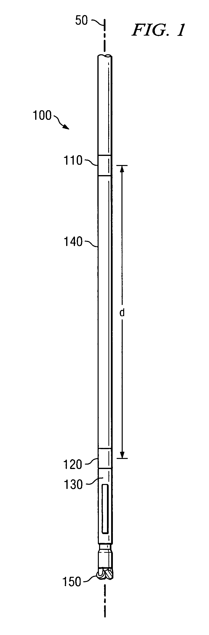
[0016] Referring now to FIG. 1, one exemplary embodiment of a downhole tool 100 according to the present invention is illustrated. In FIG. 1, downhole tool 100 is illustrated as a measurement while drilling (MWD) tool including upper 110 and lower 120 sensor sets coupled to a BHA including, for example, a steering tool 130 and a drill bit assembly 150. FIG. 1 illustrates that upper 110 and lower 120 sensor sets are typically disposed at a known longitudinal spacing ‘d’ in the downhole tool 100. The spacing ‘d’ may be, for example, in a range of from about 2 to about 30 meters (i.e., from about 6 to about 100 feet) or more, but the invention is not limited in this regard. Moreover, it will be understood that this invention is not limited to a known or fixed separation between the upper and lower sensor sets 110 and 120. Each sensor set (110 and 120) includes at least two mutually perpendicular gravity sensors, with at least one gravity sensor in each set having a known orientation wi...


PUM


Abstract

A method for surveying a subterranean borehole is provided. The method includes determining tool face angles at first and second longitudinal positions in the borehole. The method further includes processing the tool face angles to determine a change in borehole azimuth between the first and second positions. Exemplary embodiments of this invention provide a direct mathematical solution for the change in azimuth and therefore provide for improved accuracy and reliability of azimuth determination (as compared to the prior art) over nearly the entire range of possible borehole inclination, azimuth, tool face, and dogleg values.

Description

FIELD OF THE INVENTION [0001] The present invention relates generally to surveying subterranean boreholes to determine, for example, the path of the borehole. More particularly, this invention relates to the use of gravity measurement sensors, such as accelerometers, to determine a change in tool face between first and second longitudinal positions in a borehole. Such a change in tool face may be utilized, for example, to determine an azimuth of the borehole. BACKGROUND OF THE INVENTION [0002] Traditional surveying typically includes two phases. In the first phase, the inclination and azimuth (which, together, essentially define a vector or unit vector tangent to the borehole) are determined at a discrete number of longitudinal points along the borehole (e.g., at a predetermined measured depth interval). Typically, no assumptions are required about the trajectory of the borehole between the discrete measurement points to determine inclination and azimuth. In the second phase, the di...

Claims


Application Information

Patent Timeline
IPC IPC(8): E21B47/022E21B47/024G01V3/18
CPCE21B47/022E21B47/024G01V3/18
Inventor ILLFELDER, HERBERT M. J.
Owner SCHLUMBERGER TECH CORP
Why Eureka
Try Eureka