Arrangement for securely mounting an exhaust manifold to the cylinder head of an internal combustion engine

a technology for internal combustion engines and exhaust manifolds, which is applied in the direction of branching pipes, pipe elements, railway tracks, etc., can solve the problems of prolonging the life of exhaust pipes, so as to achieve the elimination of stress peaks, prolonging the service life of exhaust manifolds, and significantly reducing fuel consumption

Inactive Publication Date: 2005-12-08
BENTELER AUTOMOBILTECHNIK GMBH
View PDF6 Cites 32 Cited by
  • Summary
  • Abstract
  • Description
  • Claims
  • Application Information

AI Technical Summary

Benefits of technology

[0010] Exhaust pipes of the exhaust manifold can now be configured in an optimum manner with respect to flow dynamics. As a consequence of these gas-dynamic advantages, the exhaust counterpressure and thus fuel consumption can be significantly reduced. This in turn leads also to longer life. Uniform wall thicknesses without any indents can be manufactured so that the presence of changes in stiffness and thus stress peaks can be eliminated when the exhaust pipes are subjected to a very high operating temperature. Furthermore, the service life of the exhaust manifold can be extended by the greater freedom of the head flange to shift under the mounting rail. Such a temperature-based shift relieves the exhaust pipes of excessive stress peaks and prolongs the life of the exhaust pipes.
[0011] The tightness of the overall combination of exhaust manifold, seal, and cylinder head, is substantially improved because the screw fasteners which are applied upon the second longitudinal flange portion impose a quasi linear load on the head flange, thereby evening out the distribution of stress on the seal. Another advantage involves the suitability of the head flange for application with several motor types, because there is no need to rigidly associate the head flange to a specific screw pattern. Thus, the need for clear screw holes for torque-applying tools is eliminated.
[0012] According to another feature of the present invention, the first longitudinal flange portion of the head flange may have an S-shape configuration, with the mounting rail having an L-shaped configuration with the shoulder disposed in substantial parallel relationship to a top surface of the cylinder head and lapping over the S-shaped first longitudinal flange portion, wherein the second -longitudinal flange portion of the head flange has a flat configuration and is formed with bores for direct securement of the second longitudinal flange portion to the cylinder head by means of the screw fasteners. The L-shaped mounting rail has a wide and stable attachment leg secured to the top surface of the cylinder head by screw bolts. Suitably, the head flange may be made from a sheet metal blank by a deep-drawing process and has a thickness which is significantly smaller than a thickness of the mounting rail. As a consequence of the S-shaped configuration, the first longitudinal flange portion can be easily inserted in the longitudinal gap between the shoulder of the L-shaped mounting rail and the top surface of the cylinder head, when the head flange is tilted. Suitably, the distance between the shoulder and the top surface is greater than the thickness of the head flange. After an end surface of the first longitudinal flange portion abuts against the attachment leg of the mounting rail, the head flange can be pivoted in the direction toward the top surface of the cylinder head. As a result, a convex area of the first longitudinal flange portion contacts the shoulder of the mounting rail, resulting in a spring-elastic clamping action of the first longitudinal flange portion between the shoulder and the top surface of the cylinder head, when the second longitudinal flange portion of the head flange is directly secured to the cylinder head by the screw fasteners.

Problems solved by technology

This in turn leads also to longer life.
Such a temperature-based shift relieves the exhaust pipes of excessive stress peaks and prolongs the life of the exhaust pipes.

Method used


Image

  • Arrangement for securely mounting an exhaust manifold to the cylinder head of an internal combustion engine
  • Arrangement for securely mounting an exhaust manifold to the cylinder head of an internal combustion engine
  • Arrangement for securely mounting an exhaust manifold to the cylinder head of an internal combustion engine

Examples


Embodiment Construction

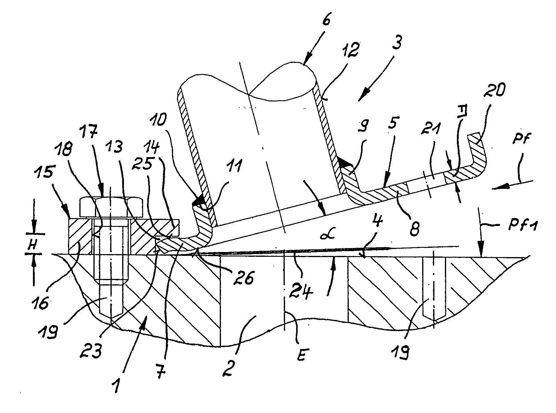
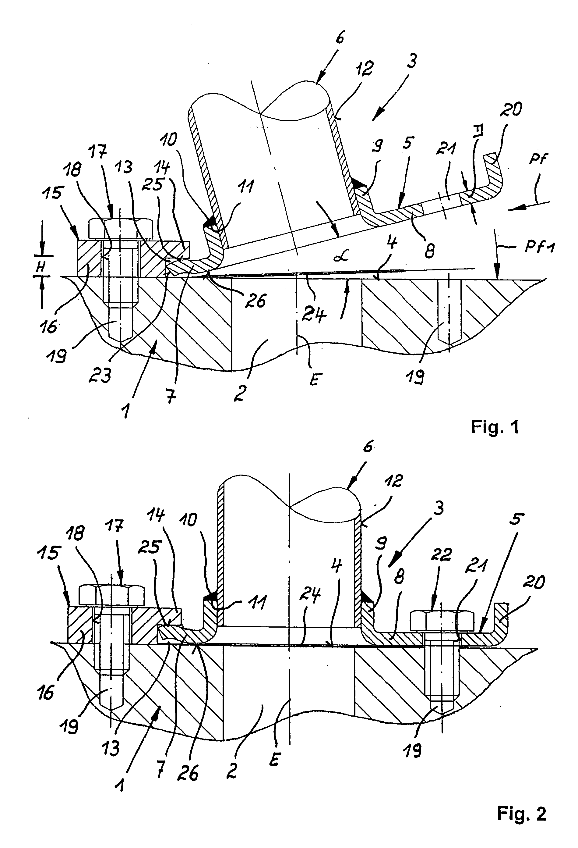
[0029] Throughout all the Figures, same or corresponding elements are generally indicated by same reference numerals. These depicted embodiments are to be understood as illustrative of the invention and not as limiting in any way. It should also be understood that the drawings are not necessarily to scale and that the embodiments are sometimes illustrated by graphic symbols, phantom lines, diagrammatic representations and fragmentary views. In certain instances, details which are not necessary for an understanding of the present invention or which render other details difficult to perceive may have been omitted.

[0030] Turning now to the drawing, and in particular to FIG. 1, there is shown a schematic vertical portion of a cylinder head, generally designated by reference numeral 1, of an internal combustion engine which is not shown here in more detail. The cylinder head 1 is provided with at least two cylinders which are arranged side-by-side and have exhaust ducts 2 oriented in a ...


PUM


Abstract

An exhaust manifold has a head flange constructed for receiving at least two exhaust pipes arranged side-by-side, and includes spaced apart first and second longitudinal flange portions. A mounting assembly is provided for sealingly securing the exhaust manifold to a cylinder head of an internal combustion engine and includes a mounting rail formed with a shoulder which laps over the first longitudinal flange portion and contacts the first longitudinal flange portion in a spring-elastic manner. Plural screw fasteners at least indirectly clamp the second longitudinal flange portion to the cylinder head.

Description

CROSS-REFERENCES TO RELATED APPLICATIONS [0001] This application claims the priority of German Patent Application Serial No. 10 2004 010 815.3 [0002] filed Mar. 5, 2004, the subject matter of which is incorporated herein by reference. BACKGROUND OF THE INVENTION [0003] The invention relates, in general, to an arrangement for secure and sealed mounting of a head flange of an exhaust manifold to a cylinder head of an internal combustion engine. [0004] German patent publication no. DE 44 30339 A1 describes an arrangement of this type, whereby a comparably thick head flange is provided with a number of openings in side-by-side disposition for receiving exhaust pipes. Both longitudinal edges of the head flange are provided with tongues that extend transversely. The tongues engage gaps in a clamping rail and a tension rail. Both, the clamping rail and the tension rail are fastened to the top surface of the cylinder head by several screw fasteners. After both rails are secured, the head fl...

Claims


Application Information

Patent Timeline
Patent Type & Authority Applications(United States)
IPC IPC(8): F01N13/10F01N13/18
CPCF01N13/10F01N13/1805F16L41/086F16L23/032F01N2450/24
Inventor SMATLOCH, CHRISTIANROSTEK, WILFRIEDBUSH, GRAHAM
Owner BENTELER AUTOMOBILTECHNIK GMBH
Why Eureka
Try Eureka