Methods and apparatus for low emission gas turbine energy generation

a gas turbine and low-emission technology, applied in the direction of lighting and heating equipment, combustion control, turbine/propulsion engine ignition, etc., can solve the problems of reducing the power output and efficiency of the plant, scr devices can be costly to install and operate, and carry the environmental risk of ammonia emission

Active Publication Date: 2005-12-08
GENERAL ELECTRIC CO
View PDF13 Cites 83 Cited by
  • Summary
  • Abstract
  • Description
  • Claims
  • Application Information

AI Technical Summary

Benefits of technology

[0006] Some aspects of the present invention therefore provide a low-emission method for producing power using a gas turbine. The method includes premixing a plurality of fuel and air mixtures, injecting the fuel and air mixtures into a combustion chamber using a plurality of fuel nozzles, and adjusting a ratio of fuel and air injected by at least one of the nozzles to control a fuel / air concentration distribution within the combustion chamber.
[0009] Configurations of the present invention will thus be seen to satisfy the latest regulatory requirement for NOx emissions for 50 Hz power equipment without requiring additional treatment of gas turbine exhaust. In addition to reducing NOx emissions, acceptable flame stability and dynamic pressure of allowable magnitude is achieved.

Problems solved by technology

SCR devices can be costly to install and operate, require expensive process chemicals such as anhydrous ammonia on a continuous basis to function, and carry the environmental risk of ammonia emission as a by-product of their operation.
While lower NOx emissions can be achieved at firing temperatures below the originally intended design ratings of a gas turbine (a process known in the art as “derating” the turbine), the power output and efficiency of the plant are reduced, ultimately resulting in lost revenue opportunity for the power producer.
Further improvements in NOx emissions have been realized using various forms of DLN technology, however, systems employing this technology have inherent operational restrictions due to combustion instability and combustion dynamic pressures or acoustic noise.
Also such systems can operate in low emissions mode only over a very limited gas turbine load range.

Method used


Image

  • Methods and apparatus for low emission gas turbine energy generation
  • Methods and apparatus for low emission gas turbine energy generation
  • Methods and apparatus for low emission gas turbine energy generation

Examples


Embodiment Construction

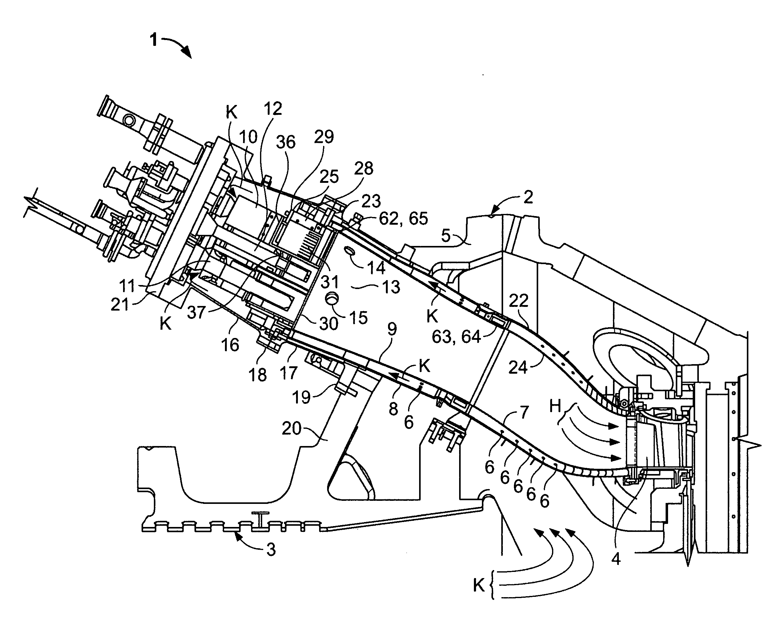
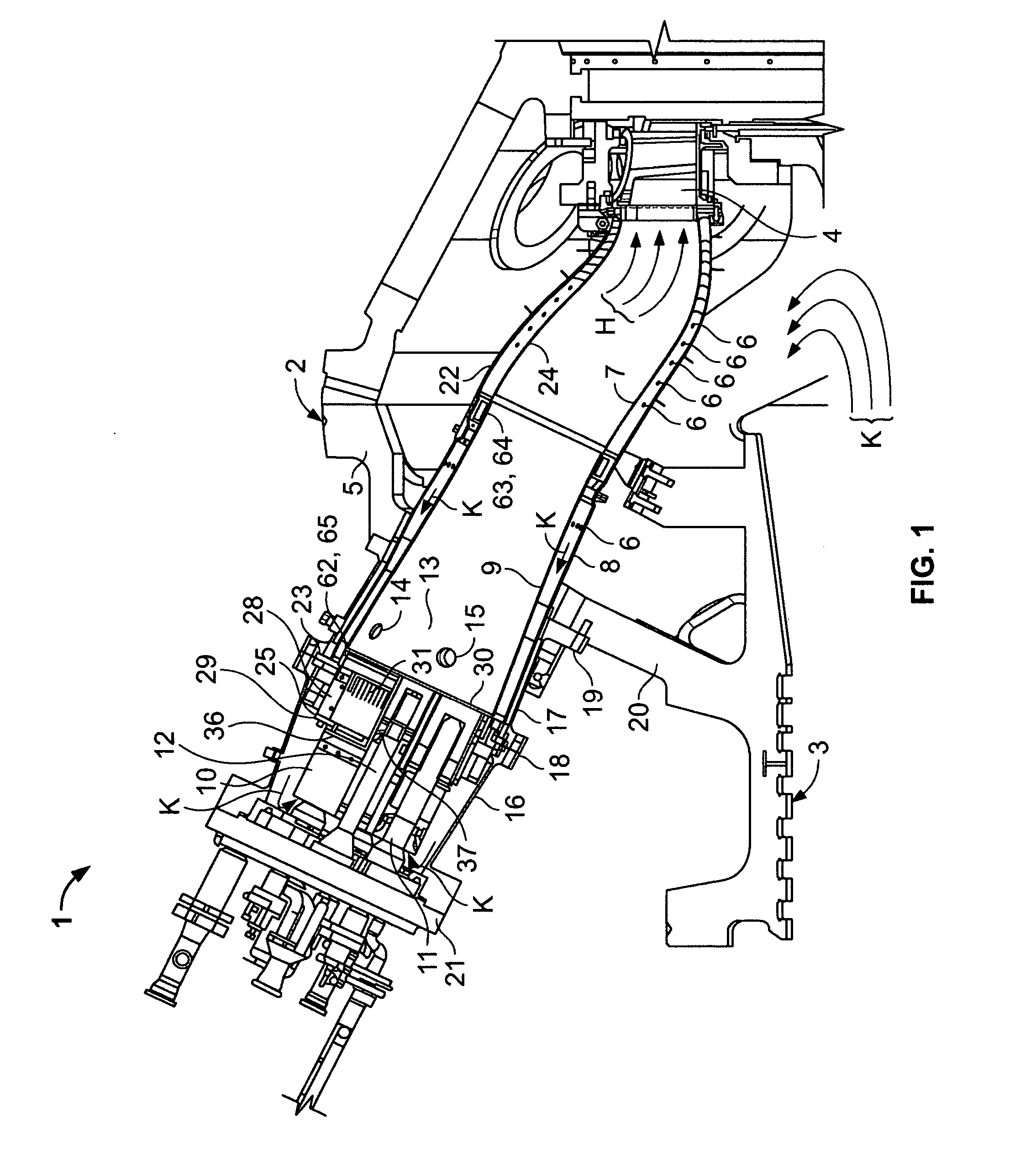
[0019] In some configurations of the present invention, a gas turbine combustion system is provided for a heavy duty industrial gas turbine to achieve one or more advantages. These one or more advantages may include: (a) low NOx and CO emissions as measured at an exhaust plane of the gas turbine; (b) acceptable flame stability in a low emissions operating mode; (c) adequate flame stability at low fuel / air ratios and lean-blow-out margin to achieve low emissions over a broad range of gas turbine load settings (for example, between approximately 35% to 100% of full rated load); and / or (d) low combustion acoustic noise (dynamic pressure fluctuations). Some configurations of the present invention meet or exceed the latest European regulatory standard of 30 mg / Nm3 NOx (approximately 14 ppm @15% oxygen corrected) emissions requirement.

[0020] One example of a currently-available gas turbine model useful in conjunction with configurations of the present invention is the General Electric Mo...


PUM


Abstract

A low-emission method for producing power using a gas turbine includes premixing a plurality of fuel and air mixtures, injecting the fuel and air mixtures into a combustion chamber using a plurality of fuel nozzles, and adjusting a ratio of fuel and air injected by at least one of the nozzles to control a fuel / air concentration distribution within the combustion chamber.

Description

BACKGROUND OF THE INVENTION [0001] This invention relates generally to power generation involving the combustion of gas fossil fuels, and more particularly to methods and apparatus for reducing pollutant emissions in heavy-duty gas turbine power generators. [0002] As used herein, a 50 Hz F-Class heavy-duty gas turbine refers to a gas turbine having a rated ISO day firing temperature on the order of 2400° F. (1315° C.), the highest average working fluid temperature in the gas turbine from which work is extracted, measured at the inlet plane of first rotating, work-extracting turbine blade, or bucket. Levels of NOx emissions below 9 ppm, corrected to 15% oxygen, can be achieved in such gas turbines using known premixing technology along with further enhancements to Dry Low NOx (DLN) systems currently available in the 50 and 60 Hz F-Class turbine markets. Low emission gas turbines of this type provide bluff body flame stabilization via a combination and optimization of component geomet...

Claims


Application Information

Patent Timeline
Patent Type & Authority Applications(United States)
IPC IPC(8): F02C7/232F02C9/34F23N1/02F23R3/26F23R3/28F23R3/34
CPCF02C9/34F23N2037/02F23R2900/00013F23R3/343F23R3/286F23N2237/02
Inventor AMOND, THOMAS CHARLES IIICRAWLEY, BRADLEY DONALDCHANDRASHEKAR, NATESHNAGARAJAN, BALANFEIGL-VARELA, REBECCA ARLENE
Owner GENERAL ELECTRIC CO
Why Eureka
Try Eureka