Continuous positive flow backflash prevention system

a positive flow and backflash prevention technology, applied in the direction of fire extinguishers, fluid removal, combustion processes, etc., can solve the problems of combustible gas release, the most likely to occur, and the risk of backflash in air drilling operations, so as to minimize the interruption of drilling.

Inactive Publication Date: 2005-12-08
SWARTOUT MATT
View PDF5 Cites 29 Cited by
  • Summary
  • Abstract
  • Description
  • Claims
  • Application Information

AI Technical Summary

Benefits of technology

[0014] In a broad aspect of the invention, a method for prevention of flashback from an ignition source towards a wellbore during drilling of the wellbore comprises injecting a drilling fluid into a wellbore; producing the drilling fluid from the wellbore for removing cuttings from the wellbore, the produced drilling fluid containing combustible gas; flowing the combustible gas to the ignition source for burning of said combustible gas; and continuously providing an addition fluid at a velocity of at least a minimal flame propagation velocity into the flowing combustible gas downstream of the wellbore and upstream of the ignition source for avoiding flashback from the ignition source.
[0015] In a further broad aspect of the invention, a system for the prevention of flashback from an ignition source connected to a wellbore producing unpredictable and intermittent flows of combustible hydrocarbons during drilling of the wellbore, comprises a source of addition fluid connected to the flow of combustible hydrocarbons between the wellbore and the ignition source; a venturi for accelerating the flow of the addition fluid into the flow of combustible gas for inducing flow of combustible gas to the ignition source; wherein the addition fluid is continuously provided to the flow of combustible hydrocarbons in a velocity in excess of a minimal flame propagation velocity to prevent backflash from the ignition source to the wellbore.
[0017] In an embodiment of the invention, the venturi is positioned between a separator and the flare stack, the separator acting to provide containment of the off-gas produced with the drilling fluids and cuttings from the wellbore and to direct the gas evolved from the drilling fluids to the flare stack. The use of the separator in combination with the positive flow achieved by the addition fluid, enables drilling to proceed regardless whether “kicks” of combustible gas come from the wellbore, eliminating the need to shut the BOP's and weight up or otherwise change the drilling fluids and reducing the fear of backflash, while at the same time providing containment of gases within the separator for evolution therein and release to the flare stack without fear of gases remaining entrained and releasing at the shale shaker. The ability to drill without altering the hydrostatic head in the wellbore permits balanced and underbalanced drilling to continue and further results in being able to maintain higher ROP's.
[0019] Often drillers overlook the advantages of air drilling due to the time and costs associated with rig up and rig out of conventional air equipment implementation. A further advantage of the system of the present invention is that the system can be installed at the start of well drilling and can be used for all drilling fluid programs which might be employed, including conventional overbalanced, balanced, underbalanced and air drilling and transitions therebetween. Further, implementation of the system of the present invention minimizes drilling interruptions with changes of drilling fluids.

Problems solved by technology

The release of gas through the flare stack or blooie line is typically intermittent and has non-predictable rates, including low velocity flow, creating the potential for backflash, which is the advancing of the flame front back through the flow to the source of the gas.
During the drilling of oil and gas wells, using a variety of drilling fluids including, but not limited to air, mist, foam, aerated and liquid mud systems, the release of combustible gases is most likely to occur while drilling at balanced or underbalanced phases of well control.
Air drilling operations, whether straight air, mist or foam, are particularly at risk for backflash and, particularly so, when stopping and starting the flow of air to the wellbore while making drillpipe connections.
After connection and following commencement of the flow of air in the drillpipe, it takes some time before the air completes the circuit downhole and back to surface, thus leaving a lower gas velocity below the flare igniter and therefore creating the potential for backflash.
If the gas source of the combustible mixture is at the separator, the separator is at risk of explosion; or if the flame front of the backflash travels down into the wellbore, a downhole fire and possibly an explosion is likely, which could result in the loss of the entire well section.
Typically, conventional underbalanced separators utilize backpressure valves during balanced and underbalanced drilling operations to attempt to prevent backflash however, in some circumstances the backflash can still occur through the backpressure valve.
As drilling fluids are passed to a shale shaker, entrained gas which did not evolve in the separator can evolve at the shaker, creating a fire potential or the potential for the release of carcinogenic and toxic gases.
The backpressure valve may also result in the exertion of a higher bottom hole pressure on the formation which can interfere underbalanced drilling.
In either case, it is known in the industry that backflashes to separator vessels and into wellbores have occurred, resulting in compromise to the structural integrity of mud / gas separators and causing underground fires.
As reported by Susan Eaton in New Technology Magazine, March 2002 “Conquering Foothills Challenges—the air force”, air drilling can be dangerous, risky and costly, and underground fires are a real danger.
As suggested, successes have been realized using a combination of air and nitrogen or nitrogen alone to replace combustible mixtures with air, however providing a source of compressed nitrogen suitable for use in the volumes required for air drilling is costly and requires additional specialized equipment at surface.
Flame arrestors have been known to plug up and / or freeze as a result of cuttings and / or wet gas.
In cases where gas flow decreases or stops, venturi-type arrestors are no longer effective.
Fluid-type arrestors are prone to freezing when used in low ambient temperatures and therefore are not functional in many drilling applications.
Cessation of drilling and weighting up the drilling fluid results in lost drilling time and decreased rates of penetration (ROP).

Method used


Image

  • Continuous positive flow backflash prevention system
  • Continuous positive flow backflash prevention system
  • Continuous positive flow backflash prevention system

Examples


Embodiment Construction

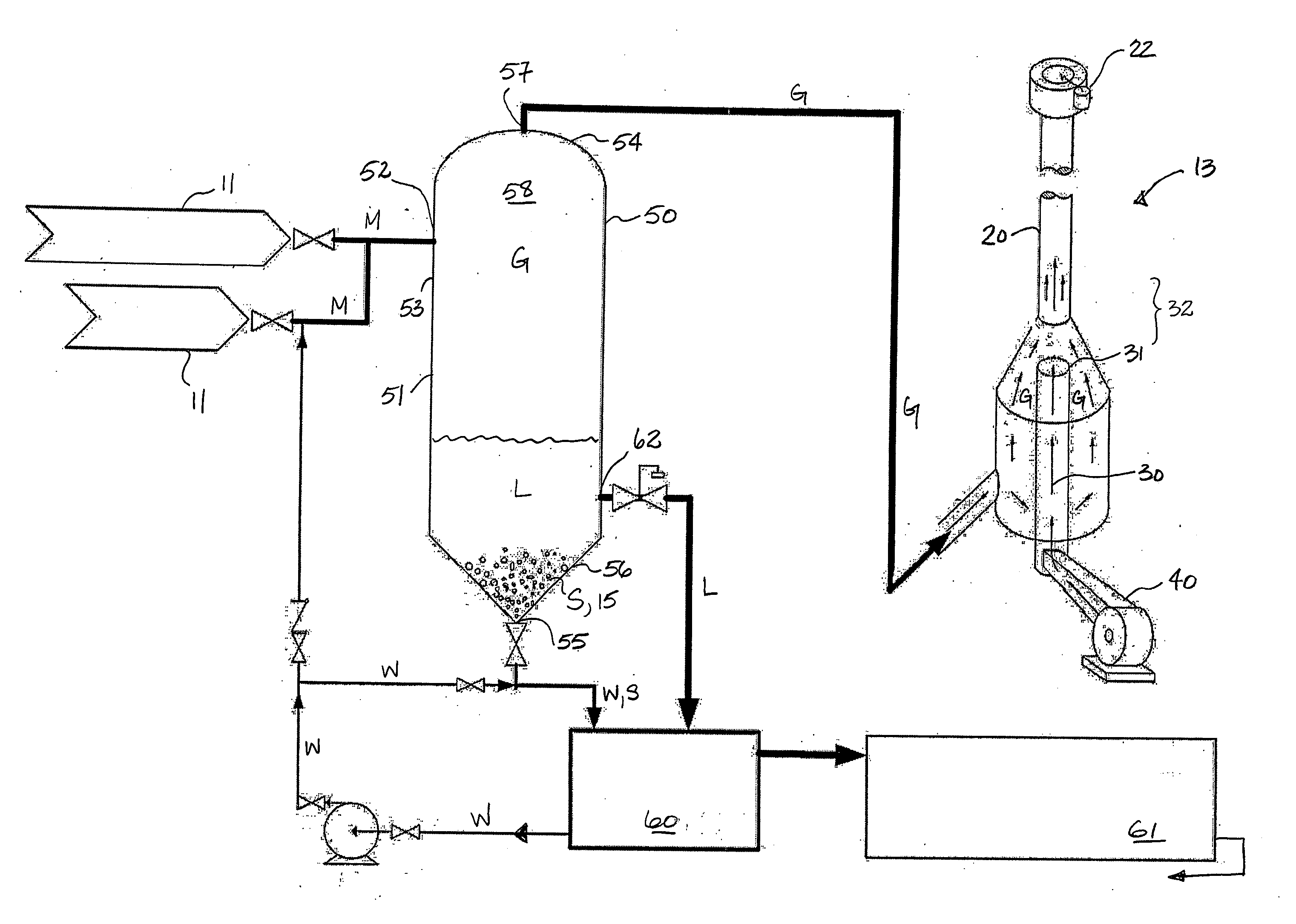
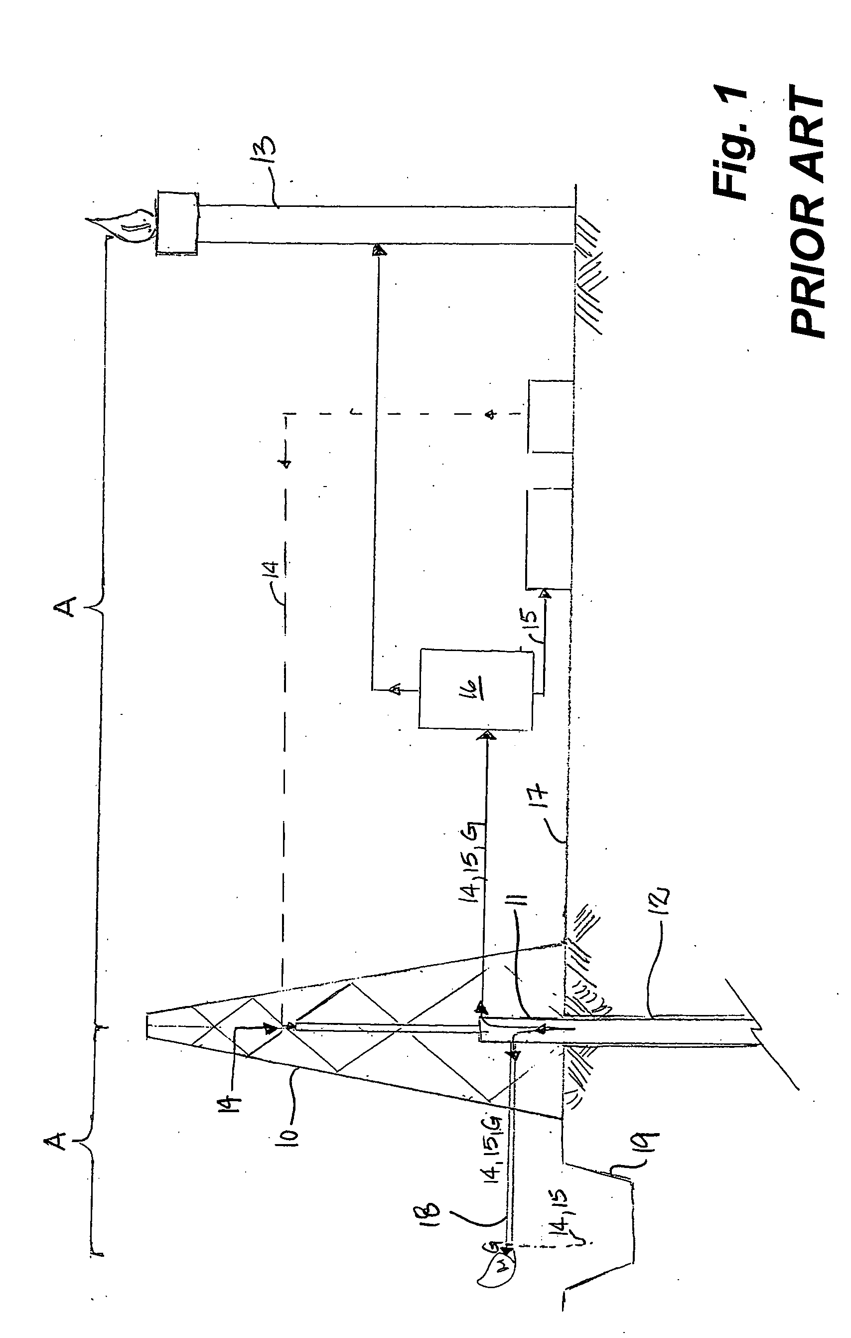
[0025] With reference to FIG. 1, a conventional drilling system comprises a drilling rig 10, a wellhead 11, wellbore 12 and a flare 13. Drilling fluids 14 are injected into the wellbore 12 to aid in extraction of cuttings 15 with the drilling fluids 14 from the wellbore 12. Suitable drilling fluids 14 include air, mist, foam or aerated mud or non-compressible liquid drilling fluids. The cuttings 15 are separated 16 from the drilling fluids 14 at surface 17. In the case where aerated mud or non-compressible mud is, the drilling fluid 14 is typically recirculated to the wellbore 12, following separation 16 of the cuttings 15. In air, mist or foam drilling, air is used to extract cuttings from the wellbore 12, in place of drilling mud. The cuttings 15 may be lifted as dust or mist should there be an influx of water into the wellbore 12. Further, agents may be added to the wellbore 12 during drilling to create a foam to aid in lifting the cuttings 15. Drilling fluids 14 returning to sur...


PUM


Abstract

A method and system for the prevention of backflash from an ignition source in a flare stack to a separator or wellbore particularly during drilling and production. A continuous positive flow of air or exhaust gas is provided into the flow of gases from the wellbore or the separator to ensure that the velocity of the flow is always higher than the velocity at which the flame can propagate backwards into either the separator or the wellbore. This method and system is particularly applicable to balanced, underbalanced and air drilling operations where the flow of gas from the wellbore is intermittent and unpredictable and can stop and start during connection and disconnection of the air used as the drilling fluid.

Description

FIELD OF THE INVENTION [0001] Embodiments of the invention relate to systems for preventing backflash from a flame source and, more particularly, to the prevention of backflash from a flame used to burn at least a portion of combustible gases from a wellbore, either directly or following separation in a separator. BACKGROUND OF THE INVENTION [0002] In the drilling of oil and gas wells and in oil and gas production facilities, flare stacks and / or blooie lines are used, through which combustible gases, offgassed from the wellbore, are released and burned. The release of gas through the flare stack or blooie line is typically intermittent and has non-predictable rates, including low velocity flow, creating the potential for backflash, which is the advancing of the flame front back through the flow to the source of the gas. [0003] During the drilling of oil and gas wells, using a variety of drilling fluids including, but not limited to air, mist, foam, aerated and liquid mud systems, th...

Claims


Application Information

Patent Timeline
Patent Type & Authority Applications(United States)
IPC IPC(8): E21B21/01E21B21/06E21B23/00E21B35/00E21B41/00E21B43/10F23G7/08
CPCF23G7/085E21B41/005
Inventor SWARTOUT, MATT
Owner SWARTOUT MATT
Why Eureka
Try Eureka