Power supply device and vehicle lamp

Inactive Publication Date: 2005-12-08
KOITO MFG CO LTD
View PDF6 Cites 36 Cited by
  • Summary
  • Abstract
  • Description
  • Claims
  • Application Information

AI Technical Summary

Benefits of technology

[0013] Further, the control circuit increases a maximum value for the current output by the secondary side until larger than twice the target value of the currents to be supplied to the loads. Thus, when the minimum value of the current on the secondary side is 0, the average value of the output current can easily approach the target value. In addition, since the control circuit changes switching frequencies in accordance with a voltage supplied by the primary side, the average current on the secondary side is maintained, regardless of the voltage supplied by the primary side. Thus, an average value for the current on the secondary side can be maintained, without the maximum value of the current on the secondary side being changed at the time an election is made using the primary switch. Accordingly, the power lost by the switching regulator can be minimized.
[0014] Furthermore, when a target value for a current to be supplied for the loads connected in par

Problems solved by technology

In this case, wherein a separate circuit must be designated for supplying a current to each row, th

Method used


Image

  • Power supply device and vehicle lamp
  • Power supply device and vehicle lamp
  • Power supply device and vehicle lamp

Examples


Embodiment Construction

[0036] Embodiments of the present invention will now be described. Note, however, that the present invention is not limited to these embodiments, and not all the feature sets described in these embodiments are always required by the present invention.

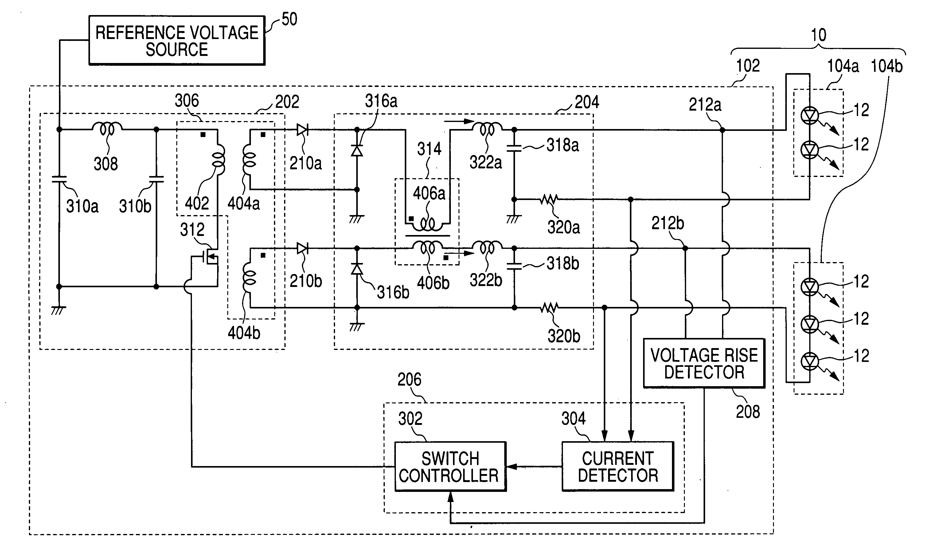
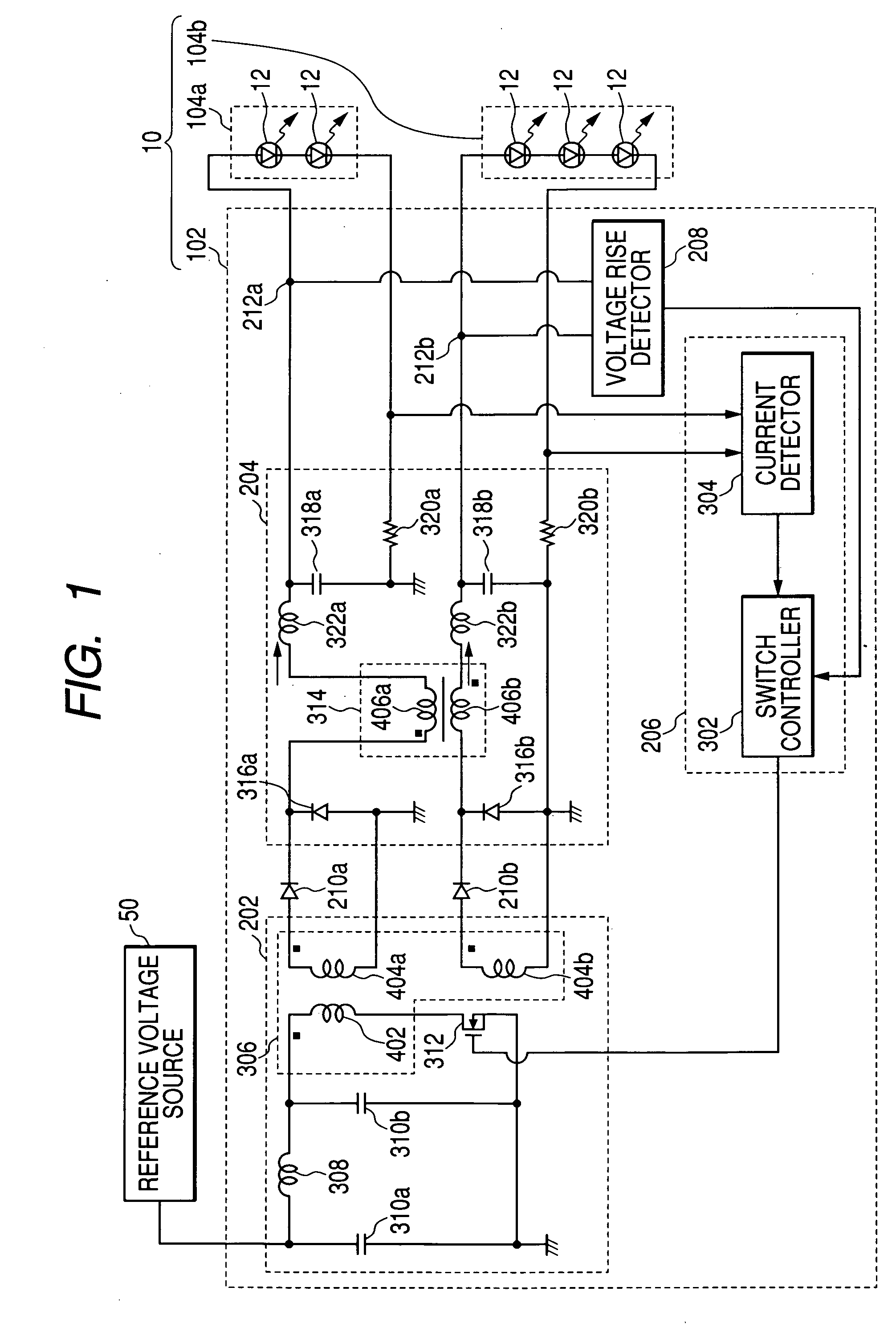
[0037]FIG. 1 is a diagram showing the configuration, according to one embodiment of the present invention, of a vehicle lamp 10 and a reference voltage power source 50. The reference power source 50, for example, is a vehicular-mounted battery that supplies a predetermined direct-current voltage to a power supply device 102. In this embodiment, the vehicle lamp 10 includes a plurality of light sources 104a and 104b and the power supply device 102. The embodiment provides a power supply device102 that can supply a current, at a desired ratio, to the light sources 104a and 104b.

[0038] The light sources 104a and 104b are example loads, connected to the power supply device 102, that are connected in parallel and include one or more light-...


PUM


Abstract

A power supply device includes: a regulator transformer; a primary switch for selectively supplying a current to the regulator transformer; a control circuit for reducing to 0, following each election made at the primary switch, the minimum value of a current output by the secondary side of the regulator transformer; and a coupling transformer for magnetically coupling routes along which a plurality of loads are connected in parallel to the secondary side of the regulator translator in a direction in which magnetic flux along each of the routes is offset by a current change. In this case, the control circuit increases the maximum value of the output current on the secondary side larger than twice of the target value of the current supplied to the loads.

Description

[0001] The present application claims foreign priority based on Japanese Patent Application No. 2004-169166, filed Jun. 7, 2004, the contents of which is incorporated herein by reference. BACKGROUND OF THE INVENTION [0002] 1. Technical Field [0003] The present invention relates to a power supply device and a vehicle lamp. [0004] 2. Related Art [0005] Conventionally, a vehicle lamp employing a light-emitting diode device is well known (see, for example, JP-A-2002-231013). When the vehicle lamp is turned on, the light-emitting diode element generates a forward voltage based on a predetermined threshold voltage at both ends. [0006] A wide discrepancy appears in the forward voltage generated by individual light-emitting diode devices. Therefore, to cope with the discrepancy in the forward voltage, the vehicle lamp should be turned on by controlling the current for the light-emitting diode device. However, there is a case wherein, because of light distribution design, a vehicle lamp empl...

Claims


Application Information

Patent Timeline
IPC IPC(8): G05F1/46B60Q1/00H02M3/28H02M3/335H05B37/02H05B41/16H05B41/282H05B44/00
CPCH05B33/0815H05B45/382H05B45/35
Inventor ITO, MASAYASUMURAKAMI, KENTAROUTAKEDA, HITOSHI
Owner KOITO MFG CO LTD
Why Eureka
Try Eureka