
Method for generating harmonics free DC to ac inverters

Inactive Publication Date: 2018-03-22
ABU HAJAR AHMED FAYEZ
View PDF11 Cites 3 Cited by
  • Summary
  • Abstract
  • Description
  • Claims
  • Application Information

AI Technical Summary

Benefits of technology

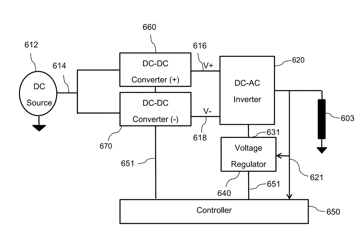
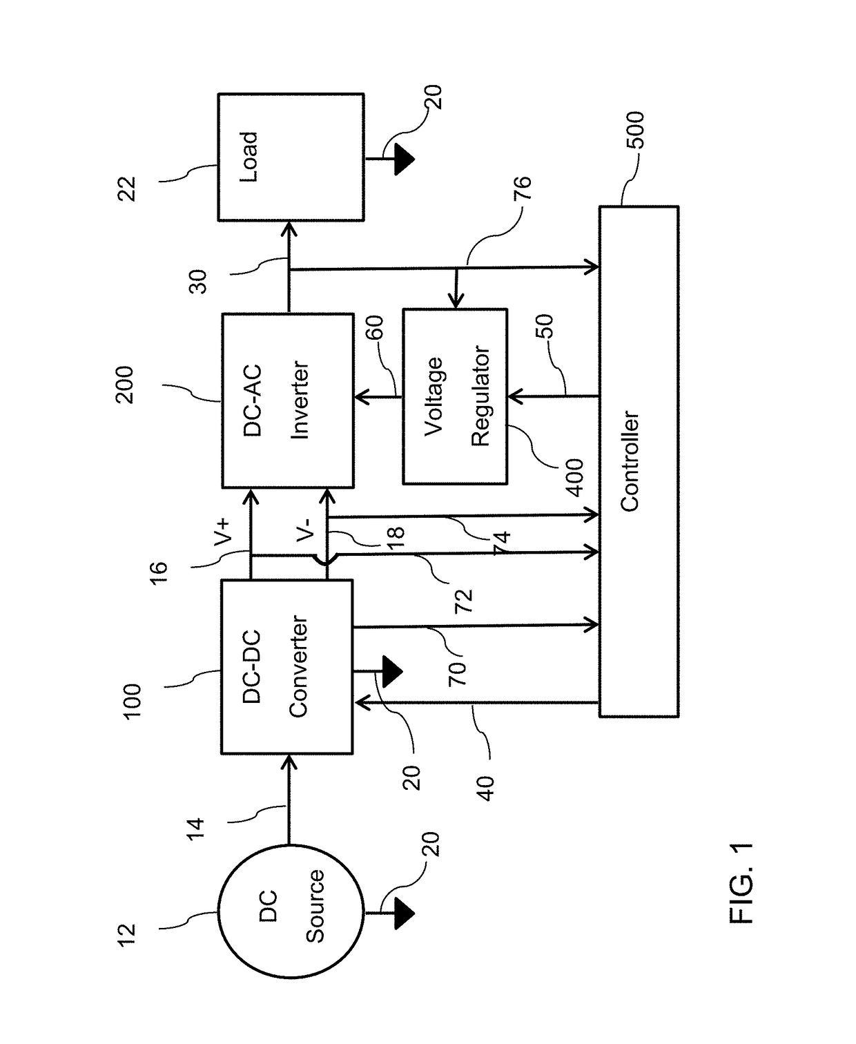
This patent describes a method that helps minimize power losses in electronic circuits. It uses two rails of voltage that are controlled to reduce these losses. Two different types of converters are used to achieve this. The method results in a more efficient and effective design for electronic circuits.

Problems solved by technology

However, the generated output contains harmonies due to the finite number of levels and the on / off switching.
Hence, prior arts use of expensive filters and large inductors combined with advanced pwm techniques with on / off switching.

Method used


Image

  • Method for generating harmonics free DC to ac inverters
  • Method for generating harmonics free DC to ac inverters
  • Method for generating harmonics free DC to ac inverters

Examples


Embodiment Construction

[0012]The details of this invention that are indicated in the background as well as the description herein are identified for the purpose of providing an in depth and detailed understanding of this invention. It should be clear that the exemplary embodiments may be practiced without these specific details that are described in those embodiments. In other instances, the use of the type of switches, amplifiers, and components are not limited from the ones that are shown in diagrams to facilitate the description of the exemplary embodiments. The exemplary embodiments are used herein for the purpose of illustrating certain details of this invention. However, the drawings should not be taken as imposing any limitations that may be present in the drawings. The embodiments may be implemented using an existing computer processor, or by a special purpose computer processor incorporated for this or another purpose, or by a hardwired system.

[0013]Technical effects of the method disclosed in th...


PUM


Abstract

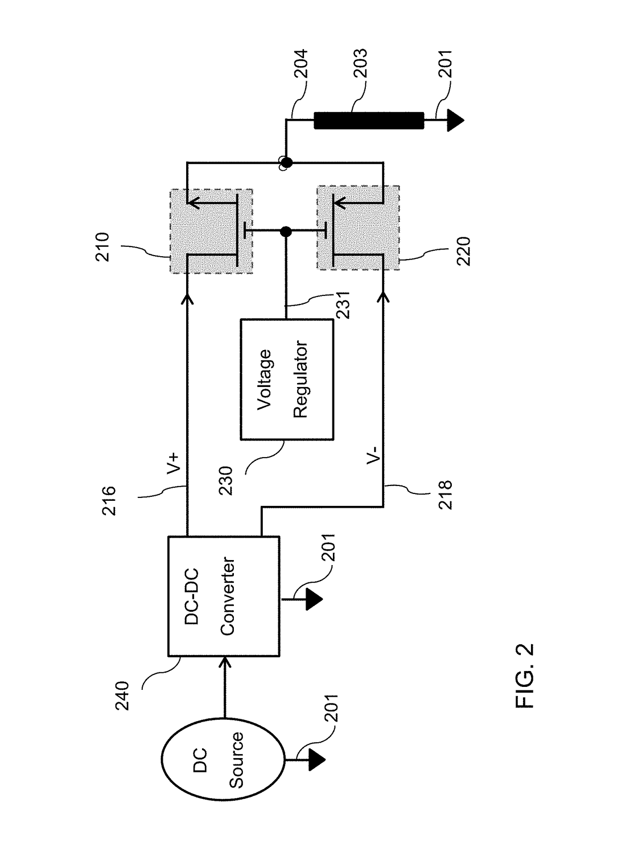
This invention presents a method that generates a harmonics free AC voltage at a specific frequency, such as 60 Hz, from unregulated DC source by precisely biasing complementary push-pull NOMS and PMOS switches. The precise bias triggering pulse is continuous pulse that is created using a feedback linear regulator. Since the feedback linear regulator uses low power electronics such as op-amps and comparators, the bias triggering pulse is stepped up using low power step-up transformer for high voltage applications. The step-up transformer is used to step-up the bias triggering pulse at the output of the feedback amplifier to drive the solid state switches precisely so that the output is harmonic free sine wave. In order to minimize the power losses by the switches, two DC-DC converters are used to control the voltages across the NMOS and PMOS switches. One DC-DC converter generates a positive voltage that is connected to the drain of the NMOS switch; where its voltage follows the output voltage during the positive half cycle of the load's current. The other DC-DC converter generates a negative voltage that is connected to the drain of the PMOS switch and it follows the output voltage during the negative half cycle of the current. Hence, a power factor controller is not needed as the NMOS automatically conducts when the load current is positive and the PMOS automatically conducts when the load current is negative. This method is applicable to a single phase as well as three phase system, and for a standalone load as well as for grid connected load. Also, this method does not require the need for a high power filter or bulky inductors to remove the harmonics as the harmonics are removed by precisely biasing each switch during its conduction.

Description

CROSS-REFERENCE TO RELATED APPLICATIONS[0001]Not applicable.BACKGROUND OF THE INVENTION[0002]This invention pertains generally to the field of electrical power conversion and particularly to DC to AC inverters using solid state switches. In this invention, a method for generating a harmonics free DC to AC inverter is created without using costly multilevel inverters and / or very large inductors to filter out the harmonics. Instead, this invention uses a voltage regulator, using a reference pure sine wave in a feedback loop, to generate a precise bias triggering pulse at the gates of the solid state switches. The precise bias triggering pulse is created such that it generates harmonics free sine wave at the output. In this invention, the bias triggered pulse is stepped up to high voltage, if needed, using very low cost and low power transformer or a cascaded sequence of series transformers. The step-up transformer sends an amplified voltage of the precise bias triggering pulse to the ...

Claims


Application Information

Patent Timeline
IPC IPC(8): H02M1/12H02M7/538
CPCH02M1/12H02M2001/0009H02M7/53803H02M1/143H02M1/0009H02M1/0045
Inventor ABU-HAJAR, AHMED FAYEZ
Owner ABU HAJAR AHMED FAYEZ
Learn More