Method, system and apparatus for opening doors

a technology for opening doors and systems, applied in the direction of motor/generator/converter stoppers, dynamo-electric converter control, instruments, etc., can solve the problems of time-consuming wiring and the amount of time it takes to open and close the door

Inactive Publication Date: 2005-12-08
THE CHAMBERLAIN GRP INC
View PDF10 Cites 23 Cited by
  • Summary
  • Abstract
  • Description
  • Claims
  • Application Information

AI Technical Summary

Benefits of technology

[0007] It is an object of the invention to provide a garage door opener that has a motor speed ramping function to provide a gradual increase in motor speed from stop to full opening speed of travel, or lifting speed to provide smooth opening of the door and a then slower or ramp down soft stop to prevent damage to the door and or the opener as the door is raised.
[0008] It is another object of the invention to provide a garage door opener that has a motor speed ramping function to provide a gradual increase in motor speed from stop to full closing speed of travel, to provide smooth safe movement of the door to overcome inertia, and then to provide a “soft stop” door closure.
[0009] It is an object of the present invention to provide improved security for communication between the motor control unit and a handheld RF operational control unit and / or the RF linked operational control unit that is mounted on a structure.
[0013] It is a still further object of the invention to provide a garage door opener with an indoor control panel that connects to “off the shelf” motion sensors that cause an opener's built in lights to illuminate when motion is sensed.
[0015] It is an object of the invention to provide a garage door opener that has an improved means of controlling door movement for the purpose of detecting any obstructions, a “locked” door condition, and sensitivity of impact, utilizing a Hall pulse circuit integral with the motor.
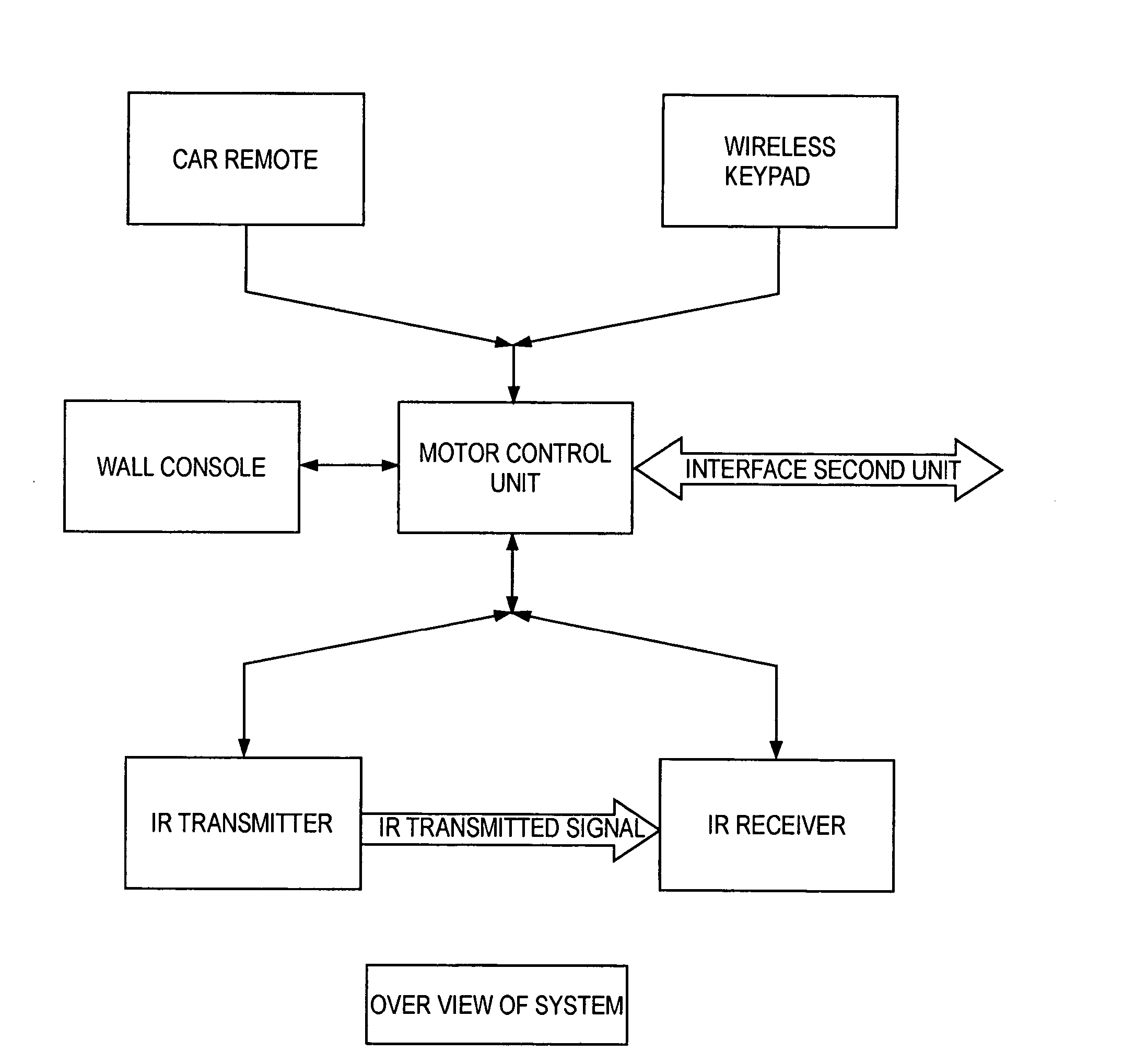
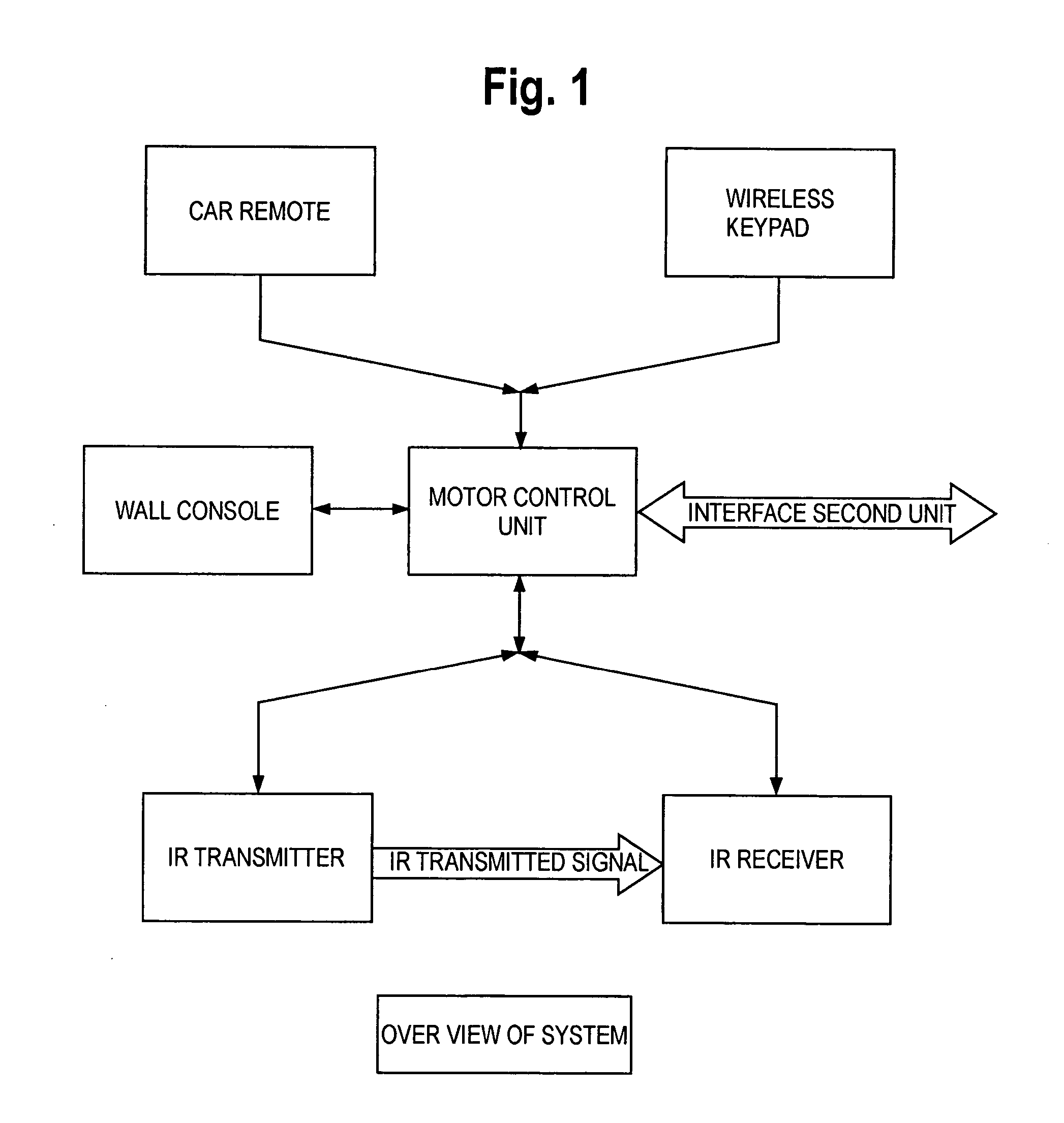
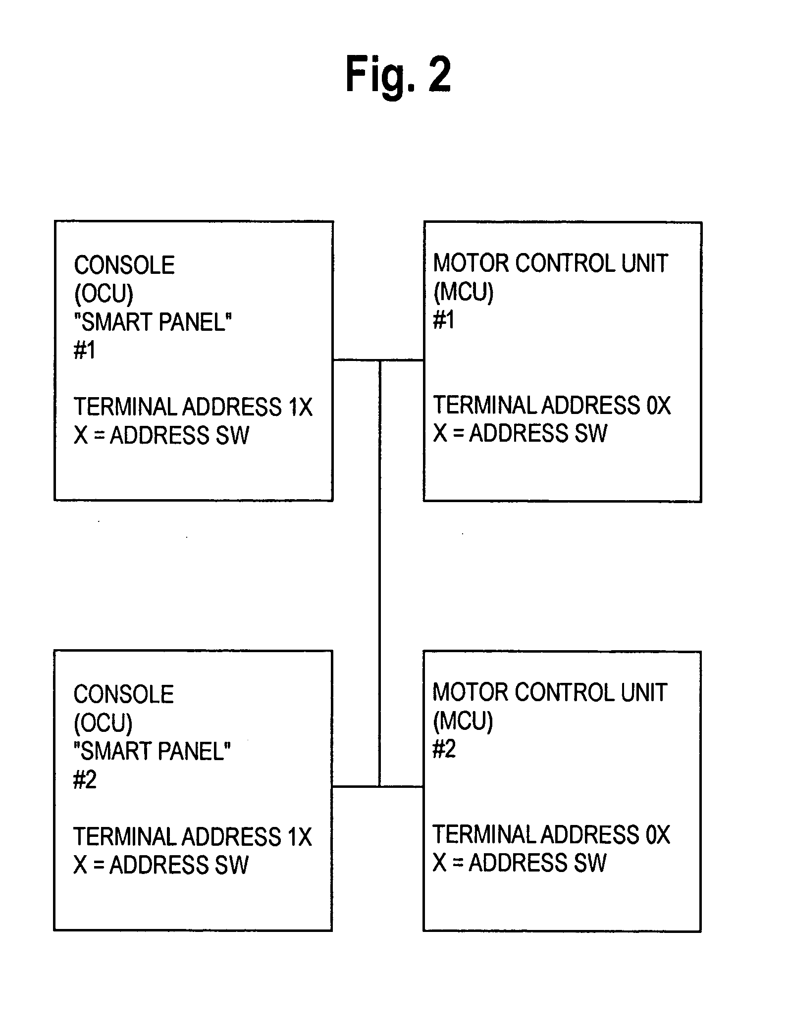
[0021] The garage door of the present invention is provided with a first microcontroller in the wall panel and a second micro controller in the drive unit. Each microcontroller has a digital serial data bus and is connected by preferably three wires because of the volume of date that is transferred from microcontroller to microcontroller. A first wire is typically a return ground wire. The second wire is used for data transfer. The third wire is for a clock. In accordance with the present invention, there may be multiple up to three drive units, i.e., openers, or wall units that may be connected together. This permits the homeowner to locate the wall units at more than one location in the garage for additional convenience.

Problems solved by technology

Running the wiring for this arrangement was time consuming and required running the wire from each opener to its respective control panel usually along one or more walls to the wall panel.
One of the issues with many current garage door openers is the amount of time it takes the door to open and close.

Method used


Image

  • Method, system and apparatus for opening doors
  • Method, system and apparatus for opening doors
  • Method, system and apparatus for opening doors

Examples


example

[0254]FIGS. 5 and 6 are schematics of the Motor Control Unit operational program. The Motor Control Unit (MCU) operational program is comprised of one main executive loop routine which controls the operations of the GDO system by handing off various control task to numerous specialized routines. FIG. 7 is a schematic drawing of the Init which is a software startup routine which sets up the operational parameters. FIG. 8 shows the Main Block which is Main Executive loop that controls the door operations.

[0255]FIG. 9 shows the Motor Block which is the Motor Control Routine which controls motor related activity of the present invention. FIG. 10, MCLOCK, is a more detailed view of the Service BUTTON, CLOCK, MEMORY, WALL CONSOLE RF REMOTE portion of FIG. 9. FIG. 11 is a schematic showing the Calc_Old_Ave (Calculating the Old Motor Current Average). FIG. 12 is a schematic showing the Calc_New_Ave (Calculating the New Motor Current Average). These calculate average motor current for use i...


PUM


Abstract

An improved garage door opener is disclosed. The garage opener has a motor drive unit for opening and closing a garage door. The motor drive unit has a microcontroller. Connected to the motor drive unit is a wall console that is located inside the garage. The wall console also has a microcontroller. The microcontroller of the motor drive unit is connected to the microcontroller of the wall console by means of a digital data bus.

Description

[0001] This application is a continuation in part of U.S. patent application Ser. No. 09 / 875,799 filed Jun. 6, 2001 now U.S. Pat. No. 6,624,605 and PCT Application Serial PCT / US02 / 18441, the disclosures of which are incorporated herein by reference.FIELD OF THE INVENTION [0002] The present invention is directed to improvements in the area of powered door opening systems, methods and apparatus. The present invention has particular application for opening and closing garage doors. BACKGROUND OF THE INVENTION [0003] Mechanized door openers have become very prevalent in homes and many commercial establishments. These devices are designed to open the door upon receipt of a signal from a keyboard, horn, pressure of tires or footsteps on a sensor etc. Garage doors are a major market for many of these devices. Garage door openers have become ubiquitous in many communities. There are a number of problems with garage door openers, however. One of the problems with garage door openers is the i...

Claims


Application Information

Patent Timeline
Patent Type & Authority Applications(United States)
IPC IPC(8): E05F15/16H02P1/00
CPCE05Y2400/80E05Y2900/106E05F15/668E05F15/41E05F15/00
Inventor PIECHOWIAK, JOHNST. PIERRE, JAMES H.
Owner THE CHAMBERLAIN GRP INC
Why Eureka
Try Eureka