Multistage amplifying devices, and reception device and transmission device using the same

a multi-stage amplifying and transmission device technology, applied in amplifiers, amplifier modifications to reduce detrimental impedence, electrical equipment, etc., can solve problems such as power consumption increase, inter-modulation distortion, and two challenges that cannot be solved simultaneously, and achieve low power consumption and remove white noise

Inactive Publication Date: 2005-12-08
PANASONIC CORP
View PDF6 Cites 11 Cited by
  • Summary
  • Abstract
  • Description
  • Claims
  • Application Information

AI Technical Summary

Benefits of technology

[0014] Therefore, an object of the present invention is to provide a low power consumption amplifier...

Problems solved by technology

In a wireless circuit of the mobile communication terminal, an amplifier circuit, a mixer circuit and the like are predominant factors for the power consumption.
Therefore, it is an important challenge for the amplifier circuit to attain a predetermined function while suppressing the power consumption.
In the amplifier circuit, for example, when a signal is input thereinto, inter-modulation distortion occurs due to signals of two bands included in the received signal.
Thus, it is also an important challenge to suppress the occurrence of IM3 in the amplifier circuit and the like.
Although the occurrence of IM3 is suppressed, power consumption increases.
Thus, the two challenges are not simultaneously solved.
However, the above-described methods have the following problems.
T...

Method used


Image

  • Multistage amplifying devices, and reception device and transmission device using the same
  • Multistage amplifying devices, and reception device and transmission device using the same
  • Multistage amplifying devices, and reception device and transmission device using the same

Examples


first embodiment

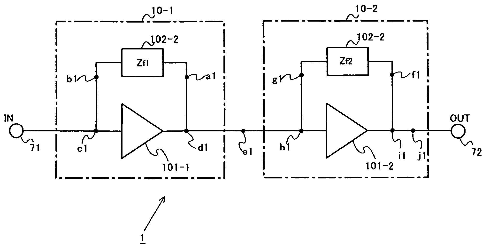
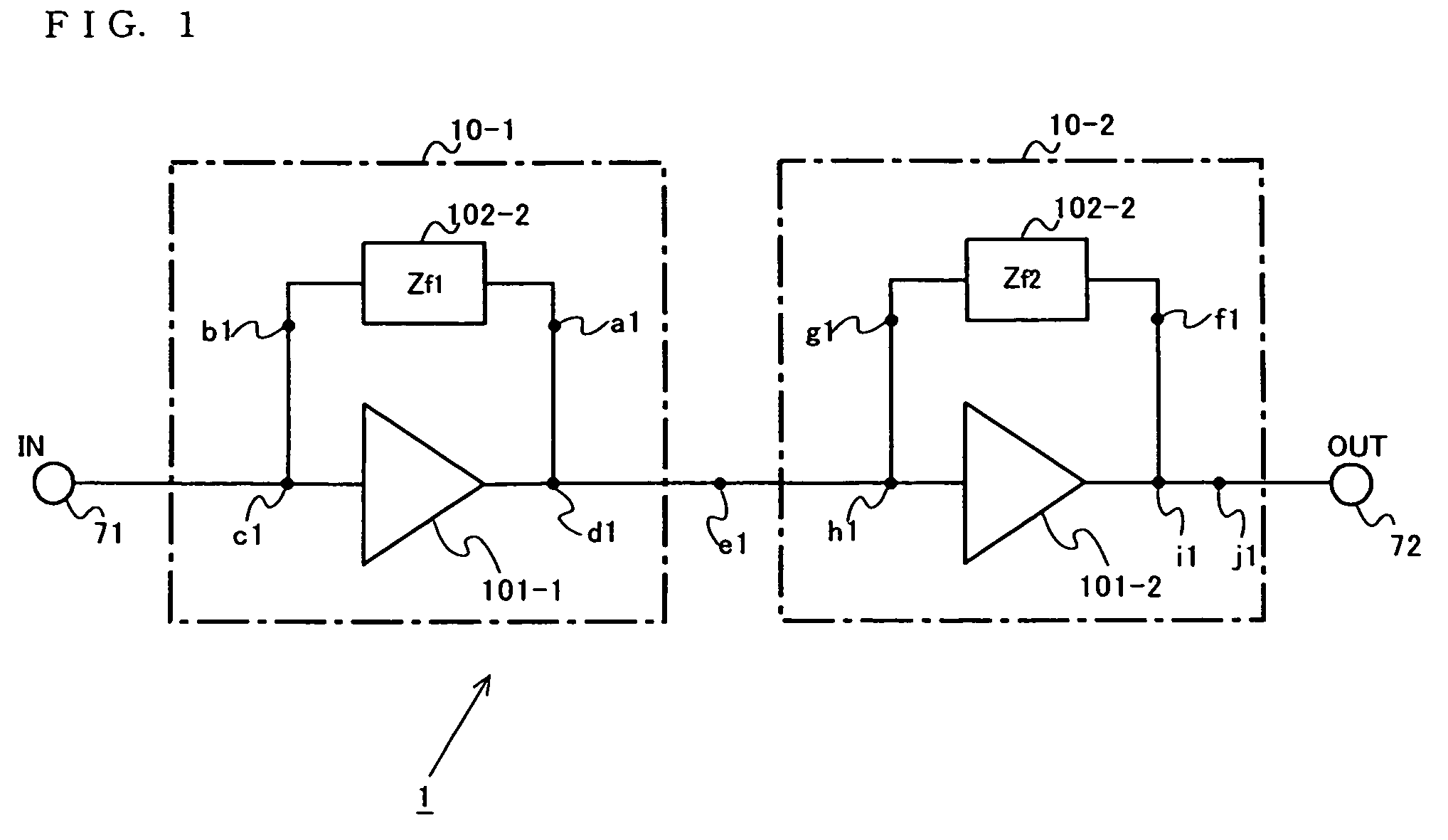
[0114]FIG. 1 is a block diagram illustrating a structure of a multistage amplifying device 1 according to a first embodiment of the present invention. In FIG. 1, the multistage amplifying device 1 comprises a first parallel feedback amplifier 10-1, a second parallel feedback amplifier 10-2, an internal terminal 71, and an output terminal 72. The first parallel feedback amplifier 10-1 includes a first amplification section 101-1, and a first parallel feedback section 102-1. The second parallel feedback amplifier 10-2 includes a second amplification section 101-2 and a second parallel feedback section 102-2.

[0115] As illustrated in FIG. 1, the multistage amplifying device 1 has the two amplifier connected in cascade, each amplifier including the parallel feedback section as a feedback circuit. The first amplification section 101-1 and the second amplification section 101-2 are inverting amplifiers. The first parallel feedback section 102-1 and the second parallel feedback section 102...

second embodiment

[0215]FIG. 10 is a diagram illustrating an exemplary structure of a multistage amplifying device 2 according to a second embodiment of the present invention. The multistage amplifying device 2 of the second embodiment of the present invention of FIG. 10 comprises a first parallel feedback amplifier 10-1, a second parallel feedback amplifier 10-2, and a third parallel feedback amplifier 10-3. In FIG. 10, the same components as those of the first embodiment are referenced with the same reference numerals as those of FIG. 1.

[0216] In the second parallel feedback amplifier 10-2 of FIG. 10, a bias circuit 216 is explicitly illustrated. The bias circuit 216 is connected to the base of the third transistor 211 and the base of the fourth transistor 212.

[0217] As illustrated in FIG. 10, the multistage amplifying device 2 is different from the multistage amplifying device 1 of the first embodiment in that the parallel feedback amplifier 10-3 is additionally connected in cascade. Hereinafter...

third embodiment

[0242] In a third embodiment of the present invention, a multistage amplifying device comprising first to N-th amplifiers (N is a natural number of 2 or more).

[0243] The k-th amplifier has a k-th amplification section and a k-th feedback section which has a reactance component, changes the phase of an output signal of the k-th amplification section, and feeds the resultant output signal back to the input side of the k-th amplification section. Note that, in the third embodiment, a multistage amplifying device 3 in which first to N-th parallel feedback amplifiers are connected in cascade will be described with reference to FIG. 13.

[0244]FIG. 13 is a circuit diagram illustrating a structure of the multistage amplifying device 3 of the third embodiment of the present invention. The multistage amplifying device 3 of FIG. 13 comprises the first to N-th parallel feedback amplifiers. The k-th (k is a natural number of 1 to N) parallel feedback section 10-k includes a k-th amplifier 101-k...


PUM


Abstract

A multistage amplifying device for amplifying a desired signal comprise first to N-th amplifiers connected in cascade,wherein the k-th (k is 1 to N) amplifier includes a k-th amplification section; and a k-th feedback section which has a reactance component, changes a phase of a signal output from the k-th amplification section. When a phase difference between the desired signal output from the N-th amplifier and a third-order inter-modulation distortion(IM3) output from the (N-1)-th amplifier is referred to as a first phase, and a phase difference between the desired signal output from the N-th amplifier, and a combined IM3 obtained by combining a IM3 occurring in the N-th amplification section and a IM3 fed back from the N-th feedback section is referred to as a second phase, a difference between the first phase and the second phase is 120° or more and 180° or less.

Description

BACKGROUND OF THE INVENTION [0001] 1. Field of the Invention [0002] The present invention relates to an amplifier and a reception device and transmission device using the same. More particularly, the present invention relates to an amplifying device with a distortion compensation function, and a reception device and transmission device using the same. [0003] 2. Description of the Background Art [0004] Recently, rapid progress has been made in improving mobile communication terminals. Particularly, various functions as well as a communication function have been incorporated into a mobile communication terminal. As the mobile communication terminal is increasingly becoming widespread, there is a keen demand for a reduction in the power consumption thereof. In a wireless circuit of the mobile communication terminal, an amplifier circuit, a mixer circuit and the like are predominant factors for the power consumption. Therefore, it is an important challenge for the amplifier circuit to a...

Claims


Application Information

Patent Timeline
IPC IPC(8): H03F1/08H03F1/32H03F1/34
CPCH03F1/083H03F1/34H03F1/3276
Inventor NAKATANI, TOSHIFUMI
Owner PANASONIC CORP
Why Eureka
Try Eureka