

Display apparatus
- Summary
- Abstract
- Description
- Claims
- Application Information
AI Technical Summary
Benefits of technology
Problems solved by technology
Method used
Image

Examples
first embodiment
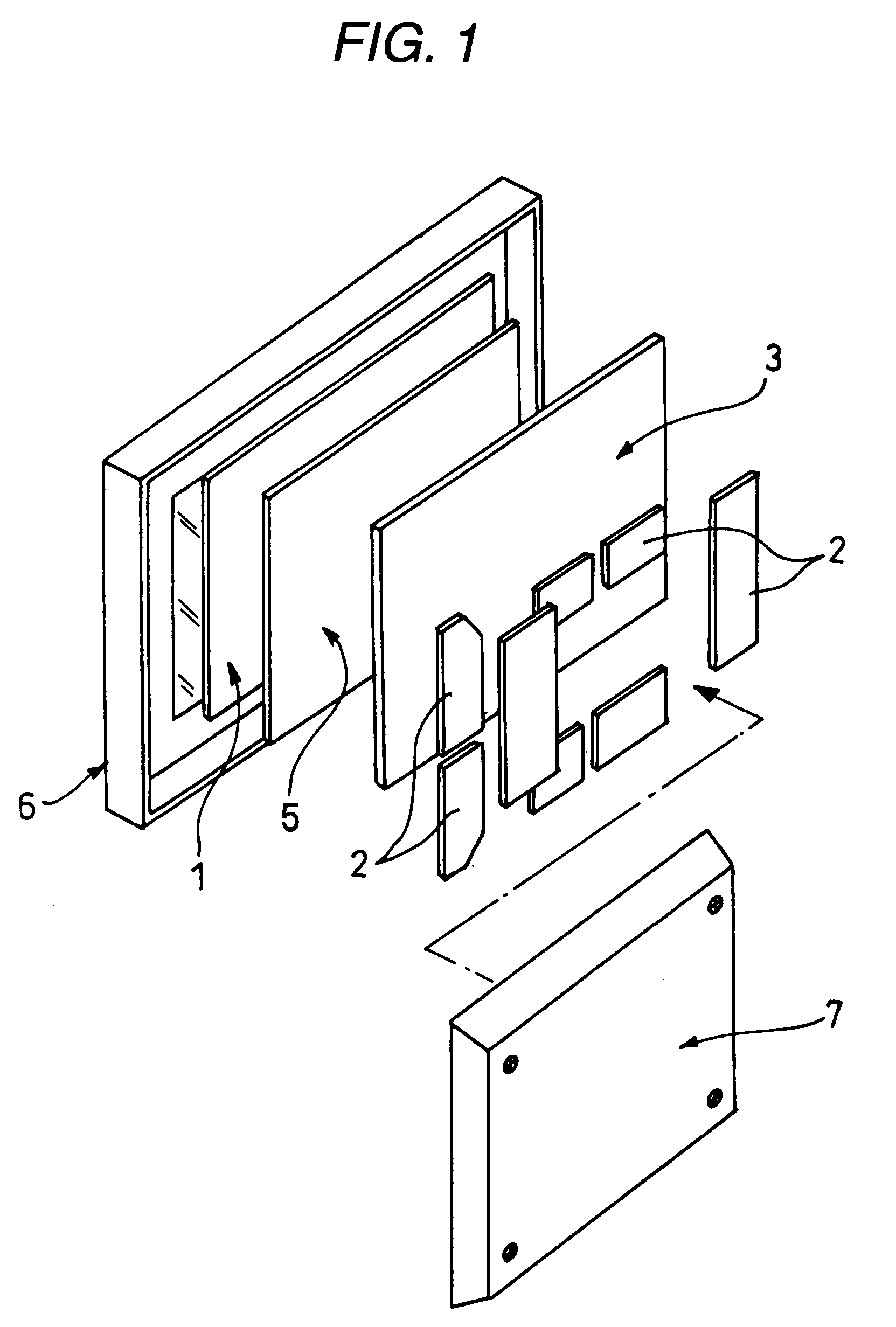
[0042]FIG. 5 is a perspective view showing a general structure of the display apparatus in a first embodiment according to the invention, and FIG. 6 is an exploded perspective view showing a connecting structure between a display panel and a chassis in FIG. 5.
[0043] As shown in FIG. 5, a case body which contains a display panel 11 in the display apparatus 10 includes a front frame 6 having an opening in which a front cover formed of glass or the like is arranged, and a rear cover 7.
[0044] The display panel 11 is held by bonding it to a peripheral part 17 (See FIG. 6 too) of a panel mounting face 13 of a chassis 12 which is formed of aluminum alloy or the like, by means of a double-faced adhesive tape 19. There are attached to a back face of the chassis 3, a plurality of circuit blocks (circuit boards) 2 such as a scan circuit board carrying a drive circuit for driving the display panel 1 to display, and a drive circuit board carrying an electric power circuit for supplying power t...
second embodiment
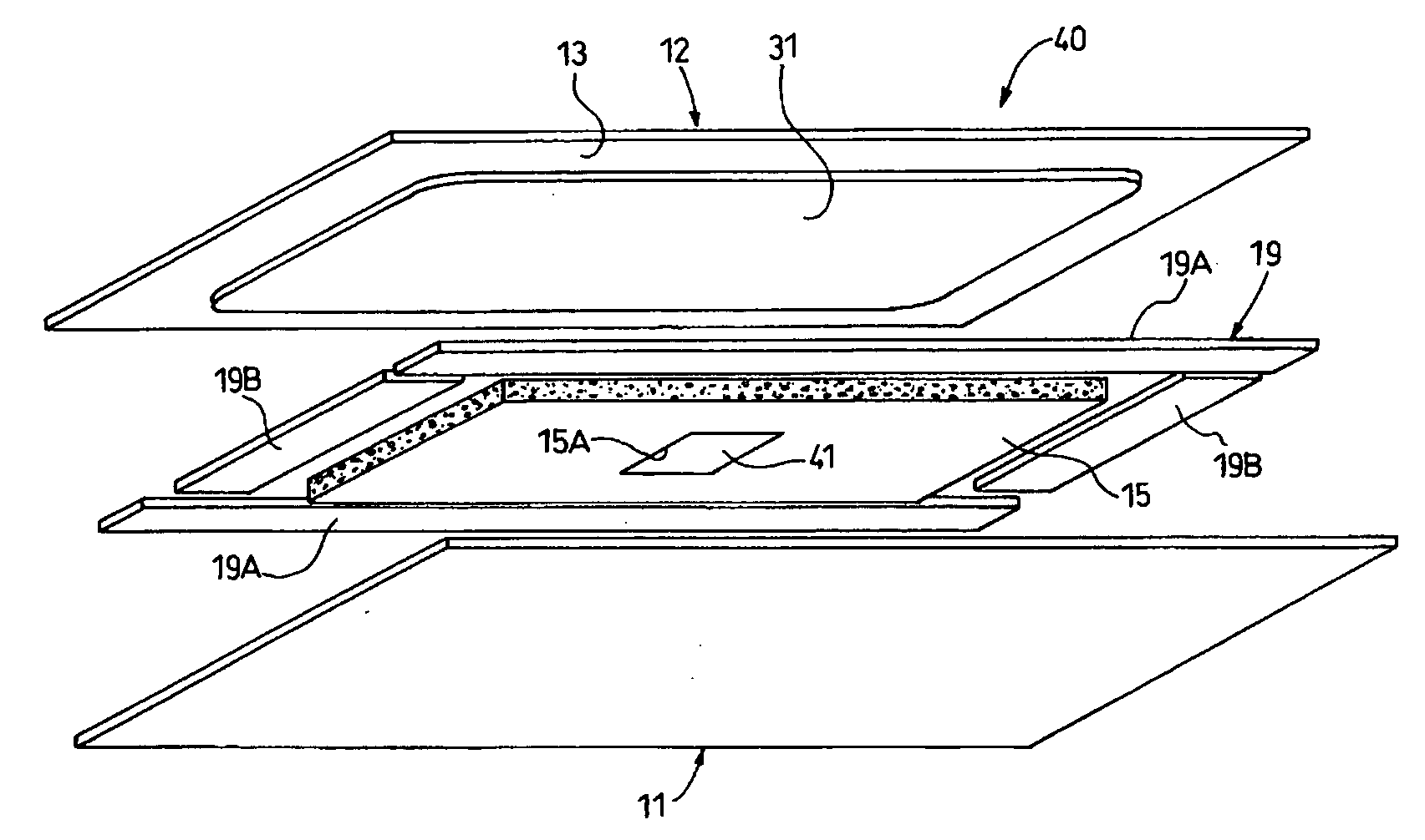
[0066] In a display apparatus 30 according to the second embodiment, the chassis 12 has a convexo-plane part 31 in a center part of the panel mounting face 13 thereof, and the foamed silicone sheet 15 is interposed between this convexo-plane part 31 and the display panel 11.
[0067] By forming the convexo-plane part 31 in the center part of the panel mounting face 13, the gap between the display panel 11 and the chassis 12 can be made smaller. As the results, thickness of the foamed silicone sheet 15 can be reduced.
[0068] According to the display apparatus 30 in the second embodiment, substantially same effects as the display apparatus 10 in the first embodiment can be obtained.
[0069] Additionally, according to the display apparatus 30 in the second embodiment, the thickness of the foamed silicone sheet 15 can be reduced, because the convexo-plane part 31 is formed in the center part of the panel mounting face 13. As the results, it is possible to decrease an amount of the foamed s...
third embodiment
[0077] A display apparatus 50 in the third embodiment includes the display panel 11, and the chassis 12 attached to the back face 11A of the display panel 11. The panel mounting face 13 of the chassis 12 has the convexo-plane part 31 in the center part thereof. A first double-faced adhesive tape (a second sheet having second thermal conductivity which is higher than first thermal conductivity) 51 having a first film thickness is interposed between this convexo-plane part 31 and the display panel 11, and at the same time, a second double-faced adhesive tape (a first sheet having the first thermal conductivity) 19 having a second film thickness which is larger than the first film thickness is interposed between the peripheral part 17 of the chassis 12 except the convexo-plane part 31 and the peripheral part 18 of the display panel 11.
[0078] The second double-faced adhesive tape 19 is exactly the same as the double-faced adhesive tape 19 in the first and second embodiments, but has th...
PUM
 Abstract
Description
Claims
Application Information