

Optical recording medium
a technology of optical recording medium and printing optical recording medium, which is applied in the field can solve the problems of inability to discriminate visually between optical recording mediums by manufacturers or brands, inability to design space on the label side, and user erroneous operation of optical recording mediums, etc., and achieve the effect of reducing the probability of user erroneous handling of optical recording medium, reducing design flexibility of printable optical recording medium, and reducing the probability of user er
- Summary
- Abstract
- Description
- Claims
- Application Information
AI Technical Summary
Benefits of technology
Problems solved by technology
Method used
Image

Examples
first embodiment
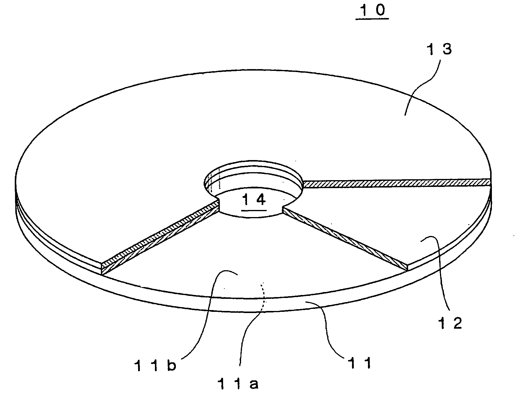
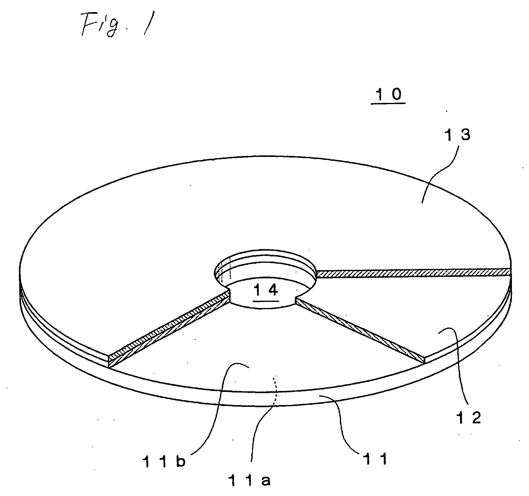
[0056]FIG. 1 is a partially cut perspective view schematically showing the appearance of an optical recording medium 10 according to a preferred embodiment of the invention.
[0057] The optical recording medium 10 according to the present embodiment is a disc-like optical recording medium having an outer diameter of about 120 mm and a thickness of about 1.2 mm. As shown in FIG. 1, the optical recording medium 10 includes a disc body 11, a printing layer 12 that is provided on a label side 11b of the disc body 11, and an ink receiving layer 13 that is provided on the printing layer 12. Further, a center hole 14 is provided at the center of the optical recording medium 10.
[0058] The disc body 11 has a light incident side 11a onto which a laser beam is irradiated when recording and / or reproducing, and the label side 11b that is a side opposite to the light incident side 11a. The disc body 11 has transparency to the extent that the label side 11b can be viewed from the light incident si...
second embodiment
[0093]FIG. 7 is a partially cut perspective view schematically showing an optical recording medium 110 according to a second embodiment of the invention.
[0094] The optical recording medium 110 according to the present embodiment is a disc-like optical recording medium having an outer diameter of about 120 mm and a thickness of about 1.2 mm. As described above, the optical recording medium 110 has a disc body 11, a first printing layer 112 that is provided on a label side 11b of the disc body 11, and a second printing layer 113 that is provided on the first printing layer 112. Further, a center hole 14 is formed at the center of the optical recording medium 110. Moreover, according to the invention, a plurality of layers provided on the label side of the disc body (in the present embodiment, the first printing layer 112 and the second printing layer 113) are collectively referred to as ‘label printing layer’. Other parts, excluding the first printing layer 112 and the second printin...
example 1
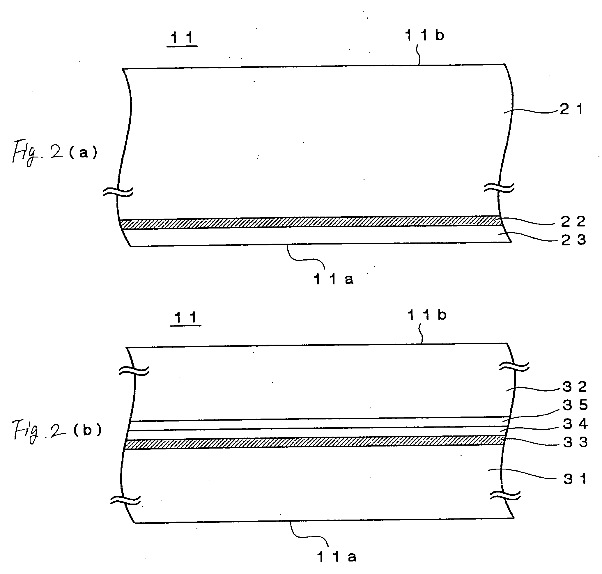
[0110] An optical recording medium having the same structure as that of the optical recording medium shown in FIG. 1 was produced by the following method. With respect the disc body, the disc having the structure shown in FIG. 2A was used.
[0111] First, a disc-like support substrate made of polycarbonate and having a thickness of about 1.1 mm and a diameter of about 120 mm was prepared by means of an injection molding method. On the surface of the support substrate, lands and grooves were formed. The depth of the groove was set to about 21 nm and the width of the groove was set to about 169 nm. The track pitch was set to about 320 nm.
[0112] Next, the support substrate was set on a sputtering device and the recording layer having a thickness of 32 nm was film-formed on the surface having the lands and the grooves by the sputtering method using a mixed target mainly containing ZnS and SiO2 and a target mainly containing magnesium (Mg). The compositions of Zn, Si, Mg, 0, and S contain...
PUM
 Abstract
Description
Claims
Application Information