Methods and systems for operating rotary machines

Inactive Publication Date: 2005-12-08
GENERAL ELECTRIC CO
View PDF7 Cites 19 Cited by
  • Summary
  • Abstract
  • Description
  • Claims
  • Application Information

AI Technical Summary

Benefits of technology

[0005] In one embodiment, a method for operating a rotary machine is provided. The rotary machine includes a stationary member and a rotatable member wherein the rotatable member is configured to rotate at least partially within the stationary member. The method includes determining an off-normal operating condition of the rotary machine facilitating undesirable contact between the rotatable member and the stationary member, monitoring a parameter associated with the off-normal operating condition, and preventing operation of the rotary machine while the monitored parameter is within a predetermined range.
[0006] In another embodiment, a control system for optimizing turbine startup procedures is provided. The turbine includes a turbine having a turbine shell, and a rotor configured to rotate about a longitudinal axis at least part

Problems solved by technology

If the clearance is too large, steam or gas flow may leak through the clearance gaps, thus decreasing the turbine's efficiency.
Alternatively, if the clearance is too small, the rotating packing seal teeth may undesirably contact the stationary packing seal or vice versa, during certain turbine operating conditions, thus adversely affecting the turbine efficiency.
Gas or steam leakage, through the packing seals represents a loss of efficiency and is generally undesirable.
However, certain off-normal operating conditions of the turbine may cause a flexure of the turbine casing, a bow in the rotor shaft, and other conditions that may cause the labyrinth seal teeth to contact other turbine components.
Such contact, known as

Method used


Image

  • Methods and systems for operating rotary machines
  • Methods and systems for operating rotary machines
  • Methods and systems for operating rotary machines

Examples


Example

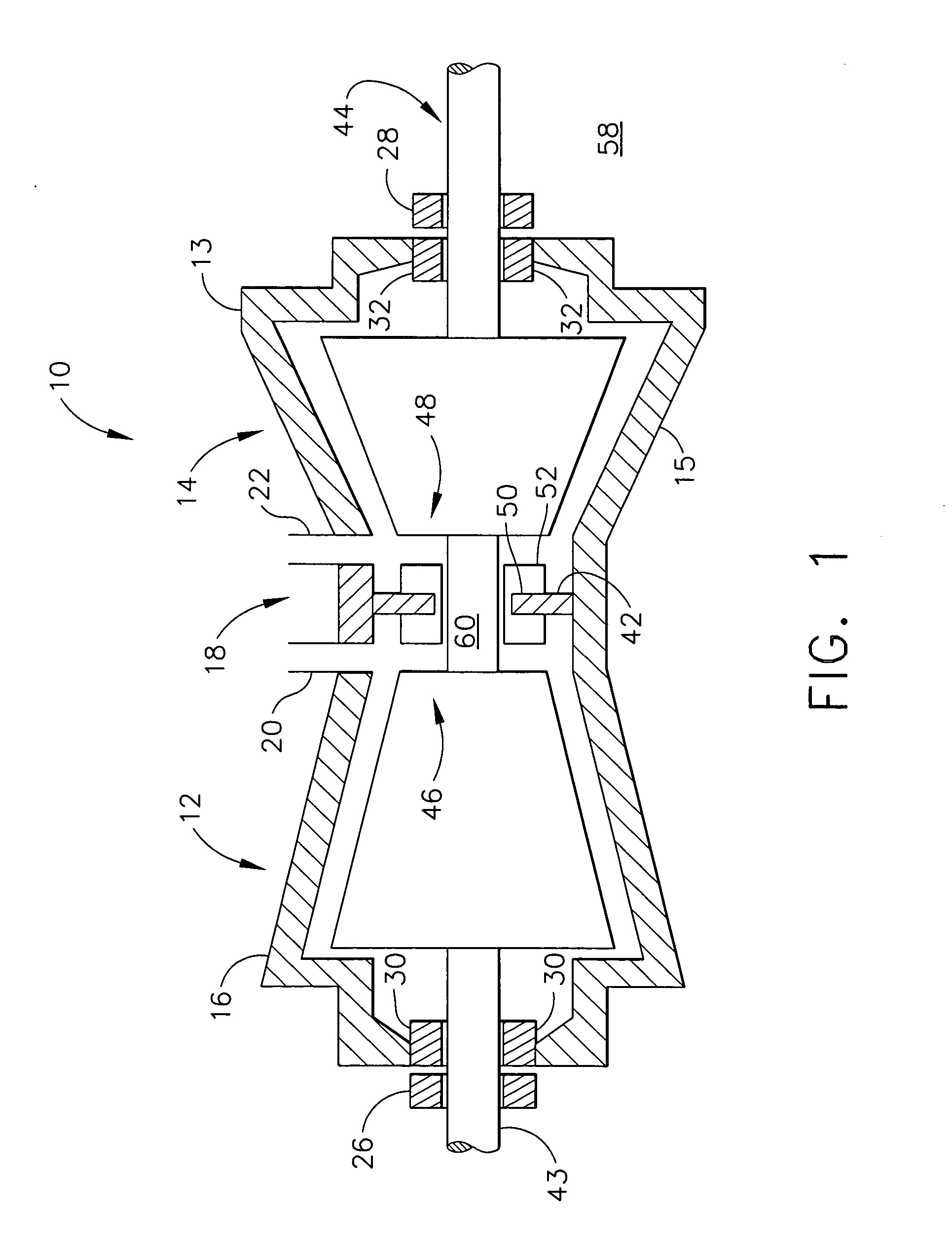
[0015]FIG. 1 is a schematic illustration of an exemplary opposed-flow steam turbine 10 including a high pressure (HP) section 12 and an intermediate pressure (IP) section 14. An outer shell or casing 16 is divided axially into upper and lower half sections 13 and 15, respectively, and spans both HP section 12 and IP section 14. A central section 18 of shell 16 includes a high-pressure steam inlet 20 and an intermediate pressure steam inlet 22. HP section 12 and IP section 14 are housed within casing 16 and are arranged in a single bearing span supported by journal bearings 26 and 28. A shaft steam seal packing 30 and 32 is located inboard of each journal bearing 26 and 28, respectively.

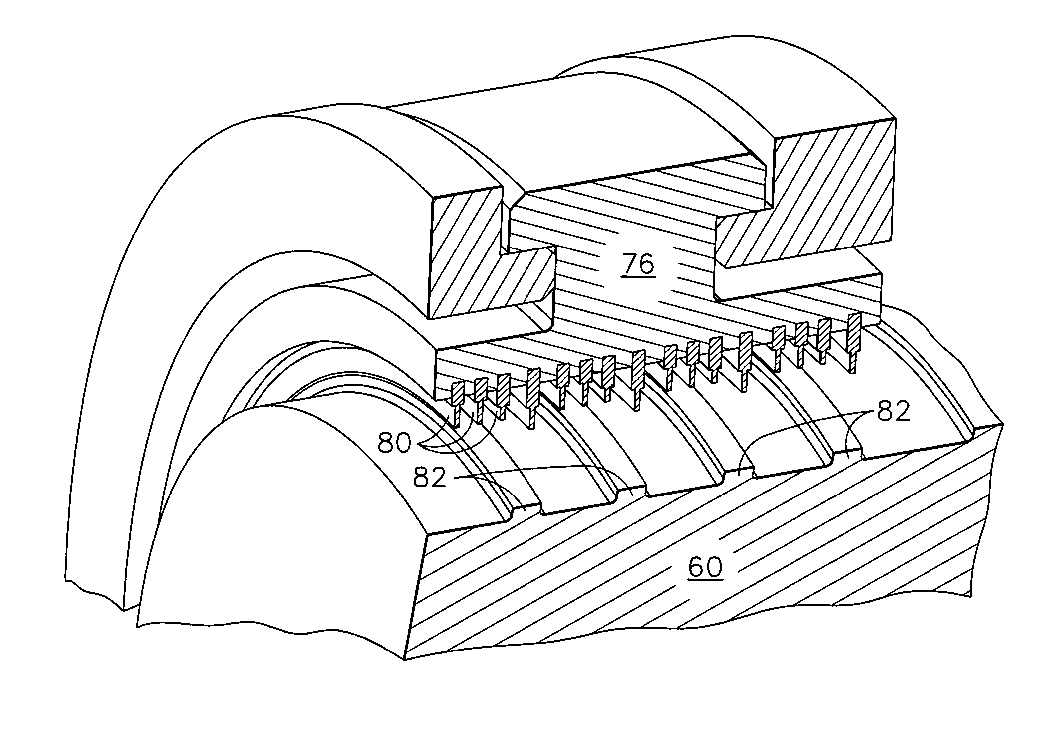
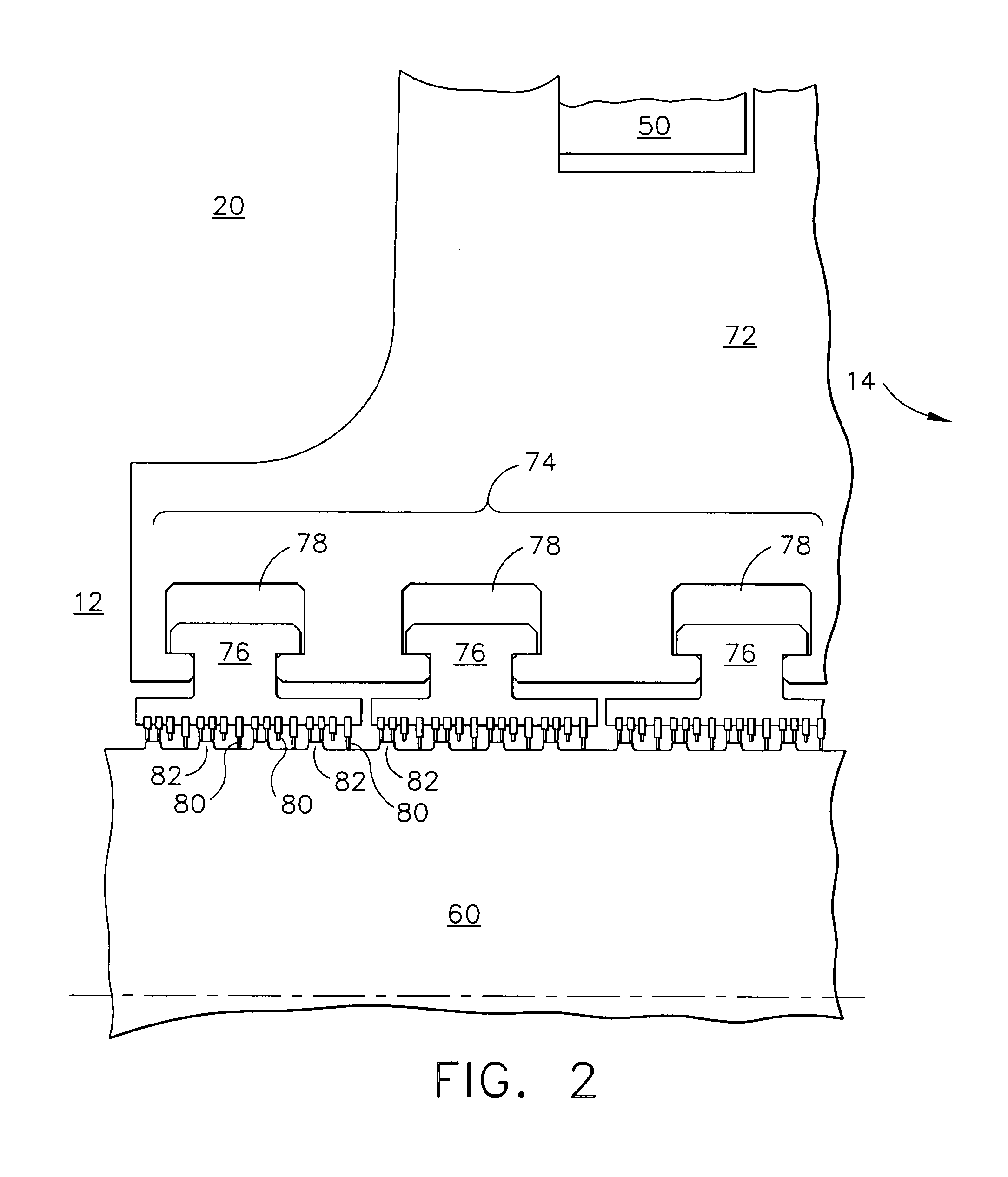
[0016] An annular section divider 42 extends radially inwardly from central section 18 towards a rotor shaft portion 60 that extends between HP section 12 and IP section 14. More specifically, divider 42 extends circumferentially around a portion of rotor shaft portion 60 between a first HP section n...


PUM


Abstract

A method for operating a rotary machine is provided. The rotary machine includes a stationary member and a rotatable member wherein the rotatable member is configured to rotate at least partially within the stationary member. The method includes determining an off-normal operating condition of the rotary machine facilitating undesirable contact between the rotatable member and the stationary member, monitoring a parameter associated with the off-normal operating condition, and preventing operation of the rotary machine while the monitored parameter is within a predetermined range.

Description

BACKGROUND OF THE INVENTION [0001] The present invention relates generally to rotary machines, and, more particularly, to methods and apparatus to facilitate sealing between rotary and stationary components within a rotary machine. [0002] Steam and gas turbines are used, among other purposes, to generate power for electric generators. Known steam turbines have a steam path that typically includes, in serial-flow relationship, a steam inlet, a turbine, and a steam outlet. Known gas turbines have a gas path which typically includes, in serial-flow relationship, an air intake (or inlet), a compressor, a combustor, a turbine, and a gas outlet (or exhaust nozzle). Compressor and turbine sections include at least one row of circumferentially spaced rotating blades or buckets. [0003] Turbine efficiency depends at least in part on controlling a radial clearance or gap between the rotor shaft and the surrounding casing or outer shell. If the clearance is too large, steam or gas flow may leak...

Claims


Application Information

Patent Timeline
IPC IPC(8): G01M99/00F01D1/00F01D11/02F01D21/00F01D21/04F01D21/14F01D21/16F01D25/00F01D25/04F01K13/00F01K13/02F02C7/00F02C9/28
CPCF01D11/025F01D21/04F01D25/04F05D2260/96F05D2270/11F05D2270/304F05D2270/305Y10S416/50F01D11/00F02C7/28
Inventor LOY, DAVID FORRESTCOOPER, GREGORY EDWARDKLUGE, STEVEN CRAIGBAKER, DEAN ALEXANDERBADAMI, VIVEK VENUGOPALEISENZOPF, PETER J.
Owner GENERAL ELECTRIC CO
Why Eureka
Try Eureka