Fuel cell and metal separator for fuel cell

a fuel cell and metal separator technology, applied in the field of fuel cells, can solve the problems of high production cost and low economic production of metal separators, and achieve the effects of preventing the insulation failure of metal separators, simple and economical structure, and achieving the desired power generation performan

Inactive Publication Date: 2005-12-08
HONDA MOTOR CO LTD
View PDF2 Cites 24 Cited by
  • Summary
  • Abstract
  • Description
  • Claims
  • Application Information

AI Technical Summary

Benefits of technology

[0010] A main object of the present invention is to provide a fuel cell and a metal separator for the fuel cell in which, with simple and economical structure, it is possible to reliably prevent insulation failure of the metal separator and maintain the desired power generation performance.

Problems solved by technology

In this case, the production cost is high, and the metal separator is not produced economically.

Method used


Image

  • Fuel cell and metal separator for fuel cell
  • Fuel cell and metal separator for fuel cell
  • Fuel cell and metal separator for fuel cell

Examples


Embodiment Construction

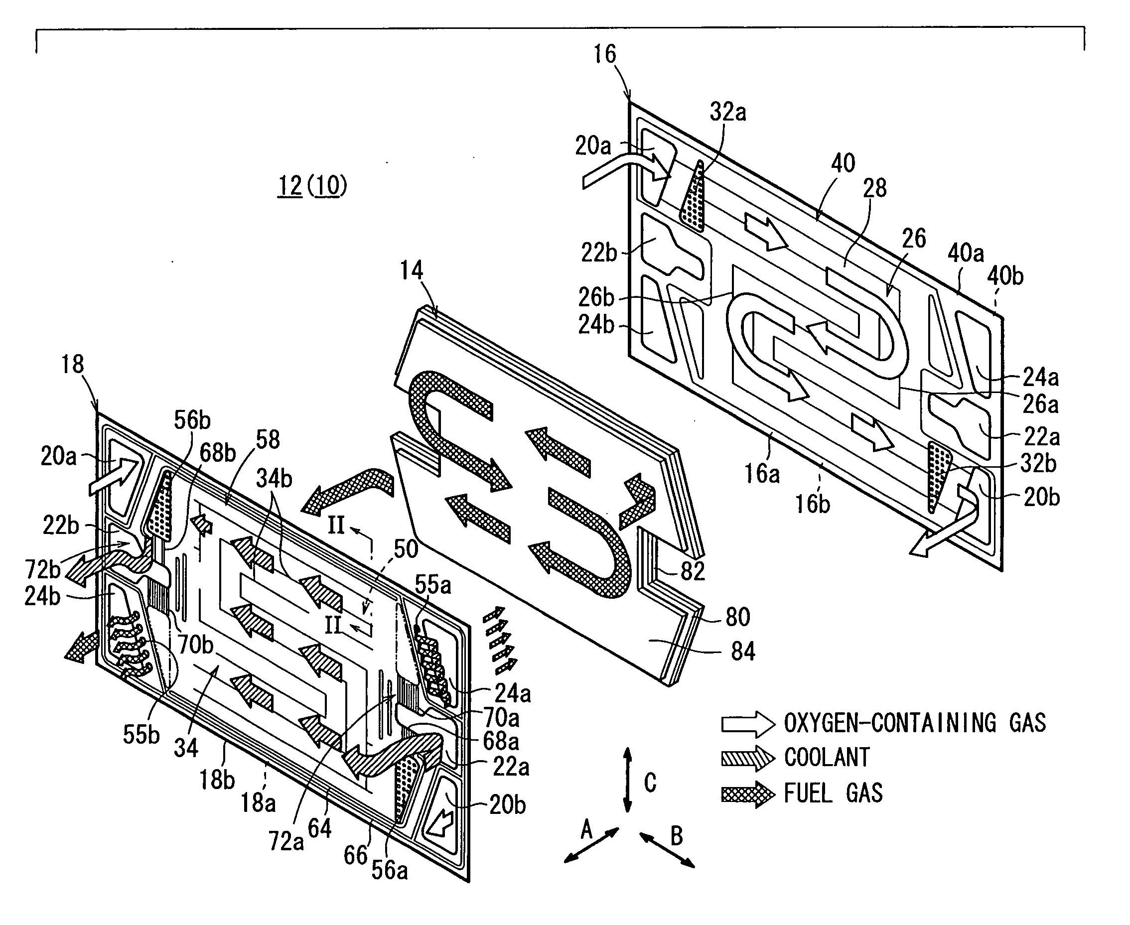
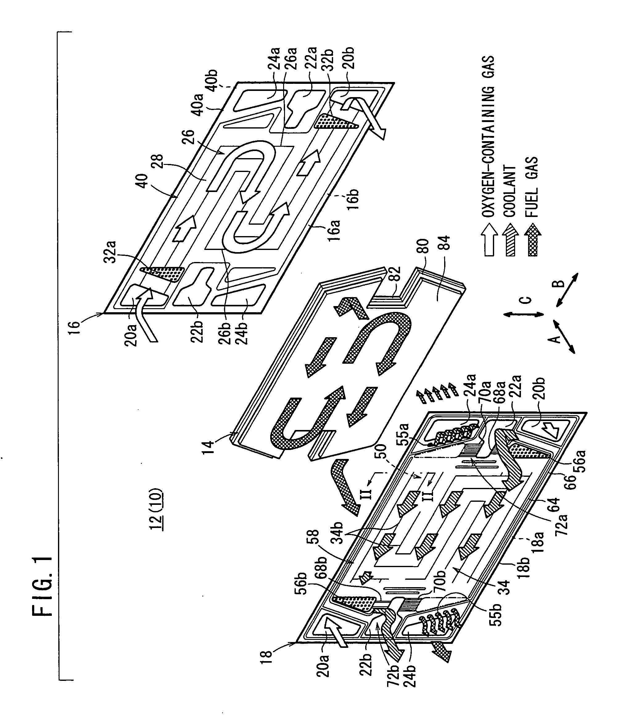
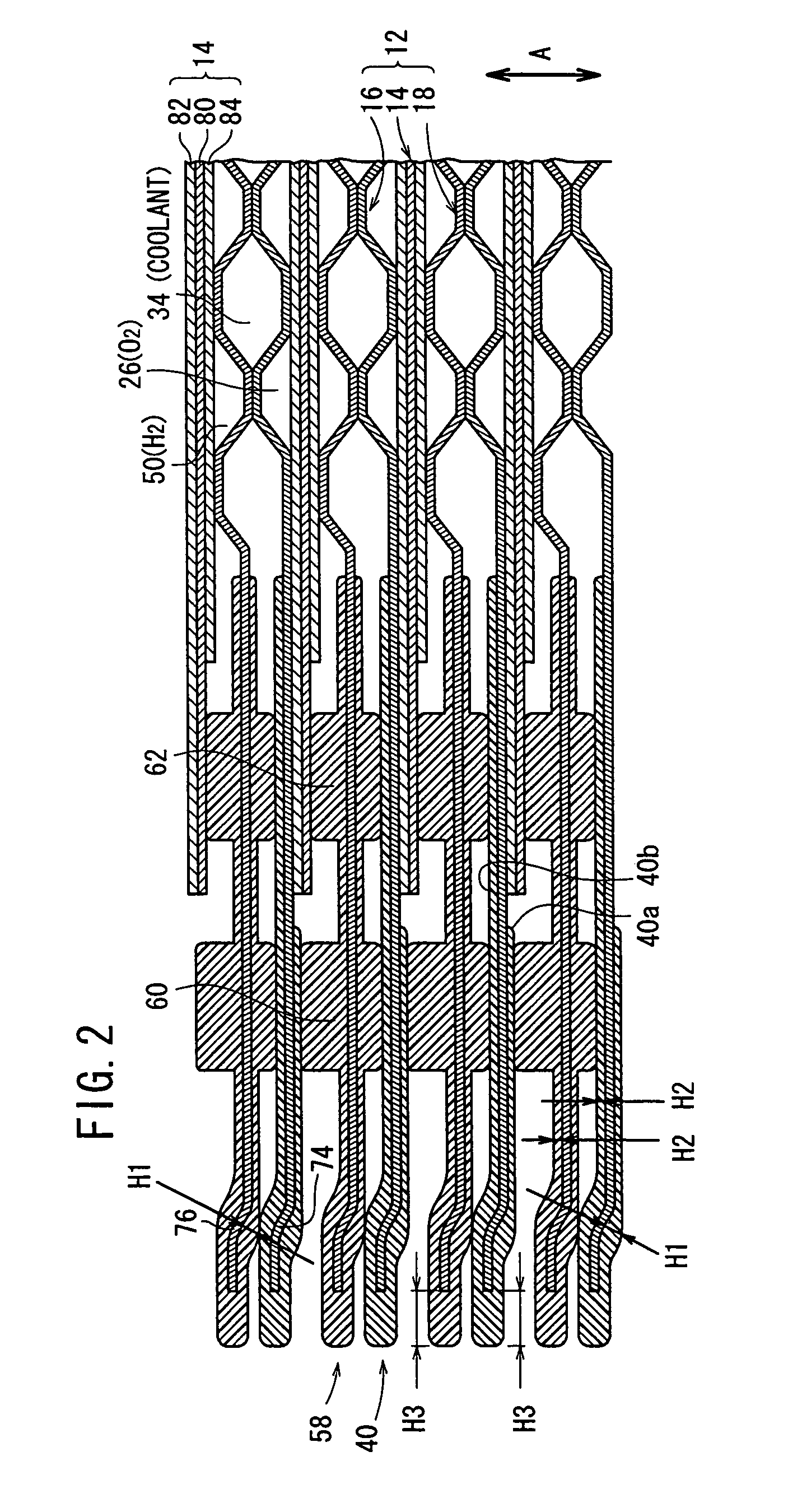
[0022]FIG. 1 is an exploded perspective view showing main components of a power generation cell 12 of a fuel cell 10 according to an embodiment of the present invention. FIG. 2 is a cross sectional view showing the fuel cell 10 formed by stacking a plurality of the power generation cells 12 in a horizontal direction indicated by an arrow A, taken along a line II-II in FIG. 1.

[0023] As shown in FIG. 1, the power generation cell 12 includes a membrane electrode assembly 14 and first and second metal separators 16, 18 sandwiching the membrane electrode assembly 14. The first and second metal separators 16, 18 are thin metal plates such as steel plates, stainless steel plates, aluminum plates, or plated steel sheets.

[0024] At one end of the power generation cell 12 in a horizontal direction indicated by an arrow B in FIG. 1, an oxygen-containing gas supply passage 20a for supplying an oxygen-containing gas, a coolant discharge passage 22b for discharging a coolant, and a fuel gas disc...


PUM

PropertyMeasurementUnit
thickness H3aaaaaaaaaa

Abstract

A power generation cell includes a membrane electrode assembly and first and second metal separators sandwiching the membrane electrode assembly. The first metal separator is a thin metal plate. A first seal member is formed integrally around the outer end of the first metal separator. A portion defining an orifice is provided in an outer marginal region of the first metal separator. The thickness H1 of the first seal member in the area covering the portion defining the orifice is larger than the thickness of the H2 of the first seal member in the area covering other portions.

Description

BACKGROUND OF THE INVENTION [0001] 1. Field of the Invention [0002] The present invention relates to a fuel cell formed by stacking a metal separator and a membrane electrode assembly including a pair of electrodes and an electrolyte membrane interposed between the electrodes. Further, the present invention relates to a metal separator for the fuel cell. [0003] 2. Description of the Related Art [0004] For example, a solid polymer electrolyte fuel cell employs a polymer ion exchange membrane as a solid polymer electrolyte membrane. The solid polymer electrolyte membrane is interposed between an anode and a cathode to form a membrane electrode assembly. Each of the anode and the cathode is made of electrode catalyst and porous carbon. The membrane electrode assembly is sandwiched between separators (bipolar plates) to form the fuel cell. In use, generally, a predetermined number of the fuel cells are stacked together to form a fuel cell stack. [0005] In the fuel cell, a fuel gas such ...

Claims


Application Information

Patent Timeline
Patent Type & Authority Applications(United States)
IPC IPC(8): H01M8/02B32B15/01H01M2/08H01M8/10
CPCB32B15/01H01M8/0206H01M8/0254H01M8/0267Y10T428/12389H01M8/0263H01M8/0273H01M8/0276Y02E60/50
Inventor SUGITA, NARUTOSHIOKONOGI, DAISUKEKIMURA, MIKIHIKOGOTO, SHUHEI
Owner HONDA MOTOR CO LTD
Why Eureka
Try Eureka