Electronic device cooling apparatus and method for cooling electronic device with temperature prediction

a technology for electronic devices and cooling apparatuses, applied in the direction of domestic cooling apparatus, semiconductor/solid-state device details, instruments, etc., can solve the problems of difficulty in efficiently cooling electronic devices, increased power consumption and noise of fans, and poor time response of temperature changes of the foregoing electric fans and heat sinks. to achieve the effect of effectively cooling an electronic devi

Active Publication Date: 2005-12-08
SONY COMPUTER ENTERTAINMENT INC
View PDF14 Cites 67 Cited by
  • Summary
  • Abstract
  • Description
  • Claims
  • Application Information

AI Technical Summary

Benefits of technology

[0009] The present invention has been achieved in view of the foregoing problems. It is thus an object of the present invention to provide a technology for cooling an electronic device effectively.

Problems solved by technology

Temperature changes of the foregoing electric fans and heat sinks typically have considerably poor time responses as compared to variations in the amounts of heat to be generated by the electronic devices.
In other words, these conventional cooling methods have had difficulties in cooling the electronic devices efficiently since the amounts of heat generated by the electronic devices can vary with time.
There have thus been the problems that the electric fans grow in power consumption and noise, and that the electric fans must have excessively large volumes.

Method used


Image

  • Electronic device cooling apparatus and method for cooling electronic device with temperature prediction
  • Electronic device cooling apparatus and method for cooling electronic device with temperature prediction
  • Electronic device cooling apparatus and method for cooling electronic device with temperature prediction

Examples


first embodiment

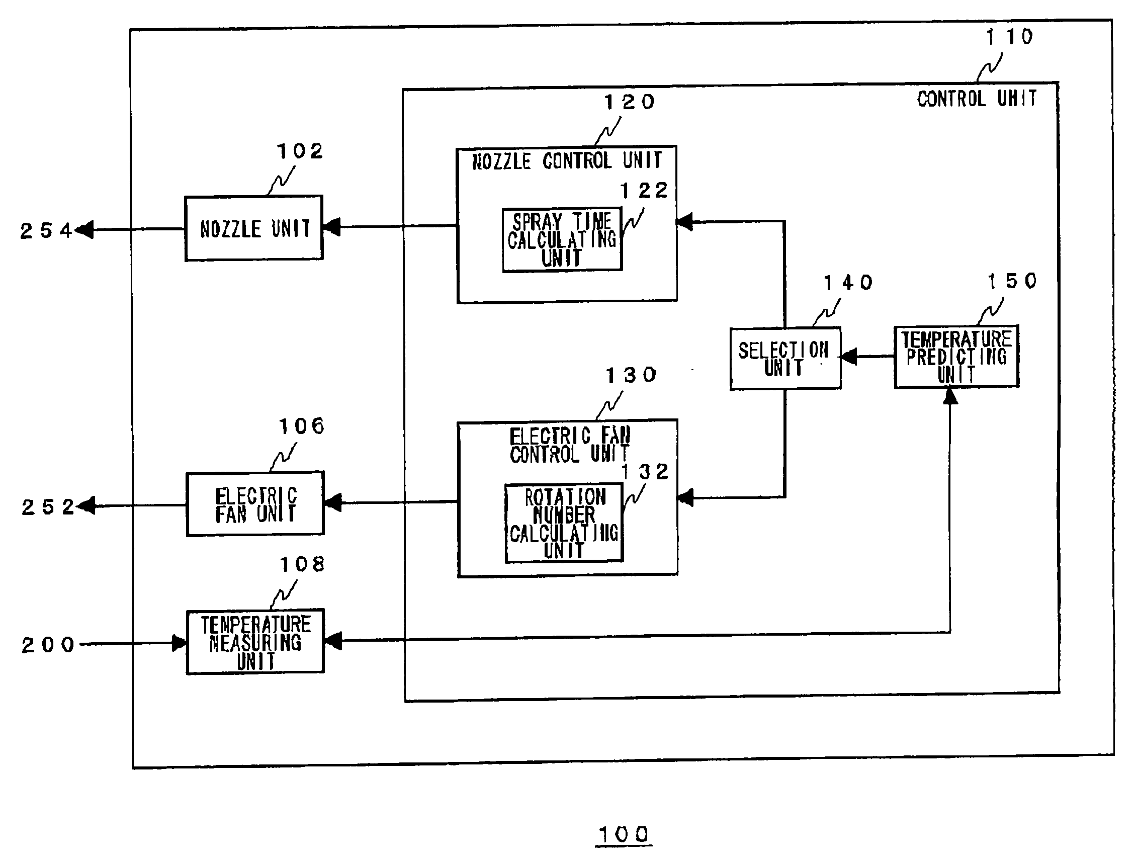
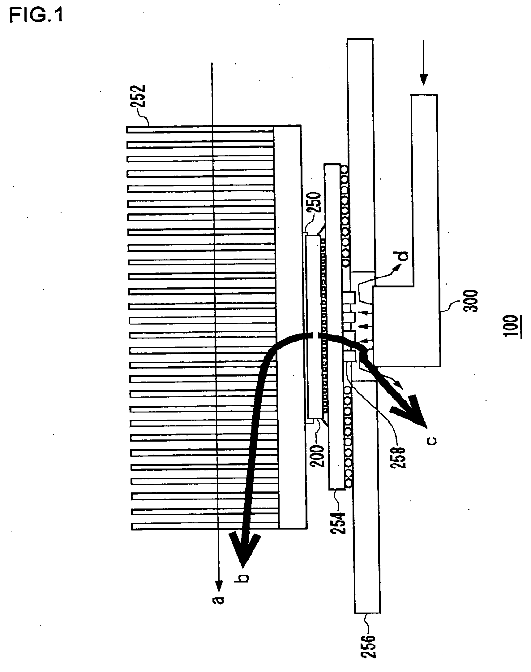
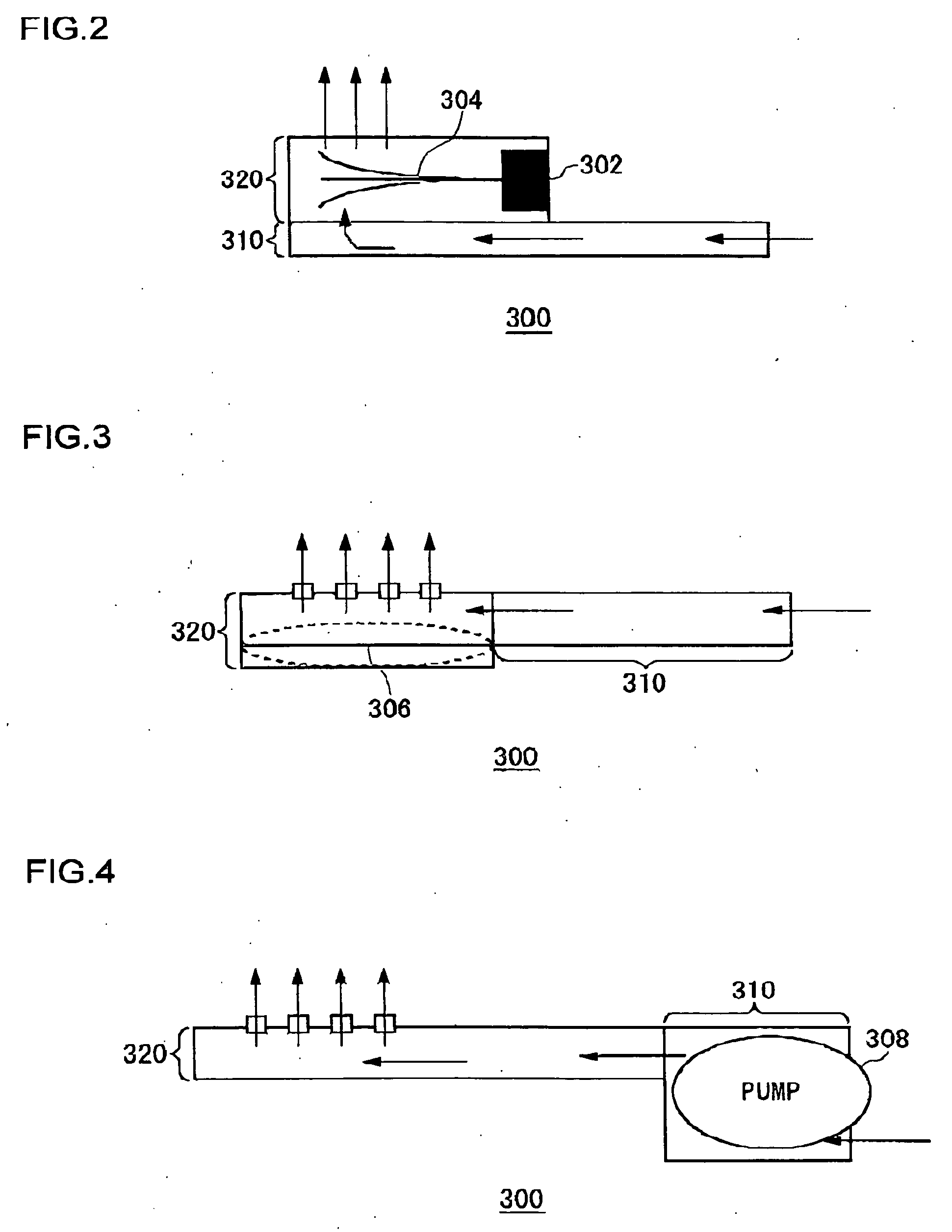
[0066] A first embodiment will deal with the case where a plurality of cooling mechanisms having different time responses are used effectively depending on predicted temperature variations. FIG. 7 is a flowchart showing the process in which the electronic device cooling apparatus 100 according to the first embodiment cools the electronic device 200. The temperature predicting unit 150 predicts the temperature of the electronic device 200 after the period Δt (S10). The selection unit 140 determines whether this predicted temperature exceeds a predetermined threshold or not (S12). This predetermined threshold is a value determined arbitrary by the designer, in accordance with the performance and the use environment of the electronic device 200. If the temperature exceeds this threshold, the proper operation of the electronic device 200 will no longer be guaranteed. Hereinafter, this threshold will be referred to as “first threshold”. If the predicted temperature is lower than the firs...

second embodiment

[0071] In the configuration of a second embodiment, the nozzle unit 102, the nozzle control unit 120, and the selection unit 140 may be omitted from the electronic device cooling apparatus 100 shown in FIG. 5. Description will be given below, assuming a typical cooling mechanism with an electric fan.

[0072]FIG. 8 is a flowchart showing the process in which the electronic device cooling apparatus according to the second embodiment cools the electronic device. Initially, the temperature predicting unit 150 sets the electric fan control unit 130 with a target control temperature Td of the electronic device 200 (S30). For example, the setting is 60° C. The temperature predicting unit 150 also passes the current temperature measured by the temperature measuring unit 108 to the electric fan control unit 130. The rotation number calculating unit 132 multiplies the difference between the set target control temperature Td and the current temperature Tt by a predetermined feedback gain k, the...


PUM


Abstract

A temperature predicting unit predicts the temperature of an electronic device after a predetermined period, and the speed of temperature variation from the operating state of the load. Based on the results of prediction by the temperature predicting unit, a selection unit instructs either one or both of a nozzle control unit and an electric fan control unit to exercise control. According to a control signal from the selection unit, the nozzle control unit transmits a control signal to a nozzle unit to drive a jet cooling apparatus. According to a control signal from the selection unit, the electric fan control unit transmits a control signal to an electric fan unit to drive an electric fan. The selection unit selects the electric fan when the predicted speed of temperature variation exceeds a predetermined threshold, and selects the jet cooling apparatus when the predetermined thresholds is not exceeded.

Description

BACKGROUND OF THE INVENTION [0001] 1. Field of the Invention [0002] The invention relates to a technology for cooling an electronic device, and more particularly to a technology for cooling an electronic device based on its surface temperature predicted in advance. [0003] 2. Description of the Related Art [0004] Electronic equipment is controlled by various types of electronic devices such a CPU (Central Processing Unit) and a DSP (Digital Signal Processor), which are made of various electronic components including active elements such as a transistor and passive elements such as a capacitor. Part of electric energy for driving these electronic components is converted into thermal energy and dissipated as heat. The performance of the electronic components typically has temperature dependence. Then, the dissipated heat has an effect on the performance of the electronic components, and by extension that of the electronic devices. Technologies for cooling the electronic devices are thu...

Claims


Application Information

Patent Timeline
Patent Type & Authority Applications(United States)
IPC IPC(8): F25D9/00F25D1/00G05D23/00H01L23/34H01L23/467H01L23/473H05K7/20
CPCG01K7/425G05D23/1917G06F1/206H01L23/34H01L23/467H01L23/4735H05K7/20172H05K7/20209H01L2224/16225H01L2224/32225H01L2224/73204H01L2224/73253H01L2924/15311H01L2924/00H05K7/20
Inventor YAZAWA, KAZUAKITAKIGUCHI, IWAOTAMURA, TETSUJIIMAI, ATSUHIKOADACHI, KENICHI
Owner SONY COMPUTER ENTERTAINMENT INC
Why Eureka
Try Eureka