Exhaust gas control apparatus and exhaust gas control method for internal combustion engine

a technology of exhaust gas control apparatus and control method, which is applied in the direction of electrical control, exhaust treatment electric control, separation process, etc., can solve the problems of insufficient fuel supply timing and the effect of the purification mechanism tending to decreas

Inactive Publication Date: 2005-12-15
TOYOTA JIDOSHA KK +1
View PDF16 Cites 12 Cited by
  • Summary
  • Abstract
  • Description
  • Claims
  • Application Information

AI Technical Summary

Benefits of technology

[0017] In the aforementioned exhaust gas control apparatus and exhaust gas control method for an internal combustion engine, detection of the flow rate of the exhaust gas flowing in the exhaust passage or the value correlated with the flow rate is performed, and the amount of the fuel to be supplied to the purification mechanism is controlled based on the result of the detection. Accordingly, even when the flow rate of the exhaust gas flowing in the exhaust passage is variously changed based on the engine operating state, the amount of the fuel to be supplied can be set based on the flow rate that is appropriately detected. As a result, it is possible to set the amount of the fuel to be supplied to a value appropriate for recovering the function of the purification mechanism while suppressing adhesion of the supplied fuel to a wall surface of the exhaust passage. Thus, it is possible to appropriately recover the function of the purification mechanism.

Problems solved by technology

While the purification mechanism is used for a long time, particulate matter (PM) and sulfur components gradually adhere to the purification mechanism, and therefore a function of the purification mechanism tends to decrease.
Therefore, even when fuel injection timing is set such that the fuel is supplied during the period in which the exhaust valve in a specific cylinder is opened, the fuel supply timing does not necessarily become appropriate for a flowing condition of the exhaust gas in the exhaust gas passage.

Method used


Image

  • Exhaust gas control apparatus and exhaust gas control method for internal combustion engine
  • Exhaust gas control apparatus and exhaust gas control method for internal combustion engine
  • Exhaust gas control apparatus and exhaust gas control method for internal combustion engine

Examples


first embodiment

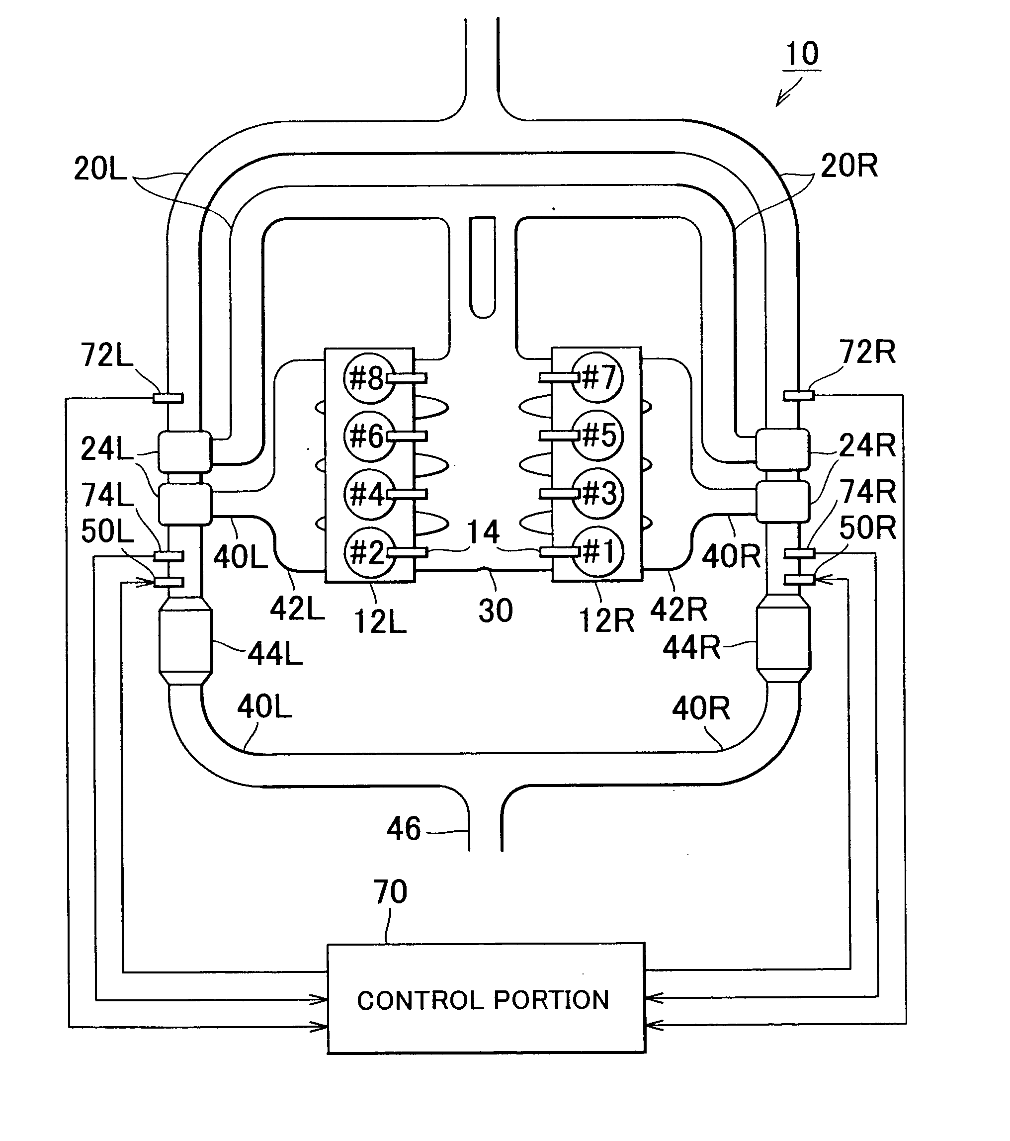
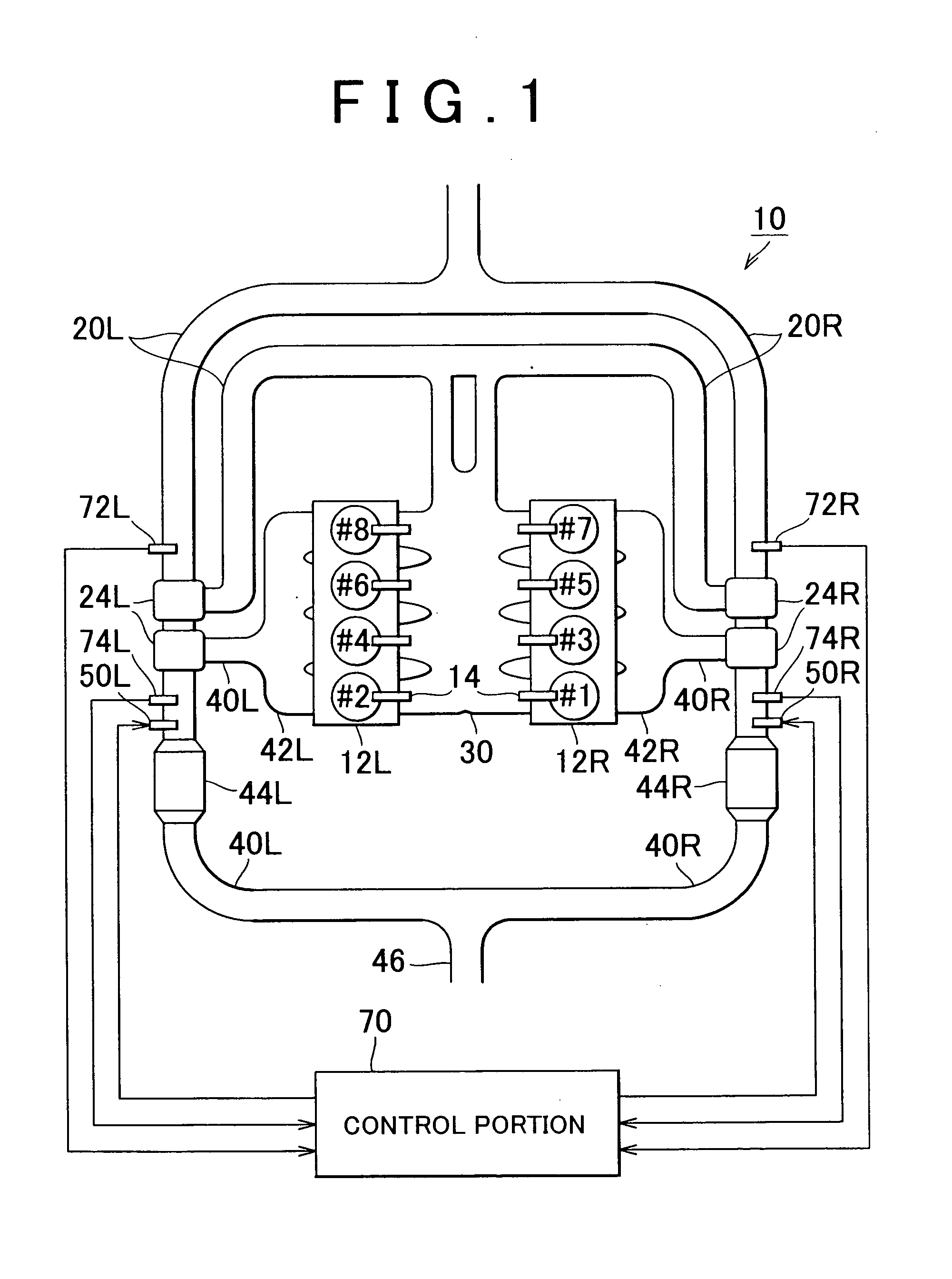
[0023] In the following description and the accompanying drawings, the present invention will be described in more detail with reference to exemplary embodiments. Hereinafter, the invention will be described with reference to FIG. 1 to FIG. 4. FIG. 1 schematically shows an internal combustion engine 10 and a peripheral mechanism thereof. As shown in FIG. 1, cylinders of the internal combustion engine 10 are arranged in a V-shape. Four cylinders are provided in a first bank (right bank) 12R, and four cylinders are provided in a second bank (left bank) 12L. Thus, eight cylinders #1 to #8 are provided in total. Fuel injection valves 14 which inject fuel are provided for the cylinders #1 to #8. The fuel injection valves 14 correspond to the respective cylinders #1 to #8.

[0024] A first intake pipe 20R and a second intake pipe 20L are connected to the cylinders #1, #3, #5, and #7 in the first bank 12R and the cylinders #2, #4, #6, and #8 in the second bank 12L through an intake manifold 3...

second embodiment

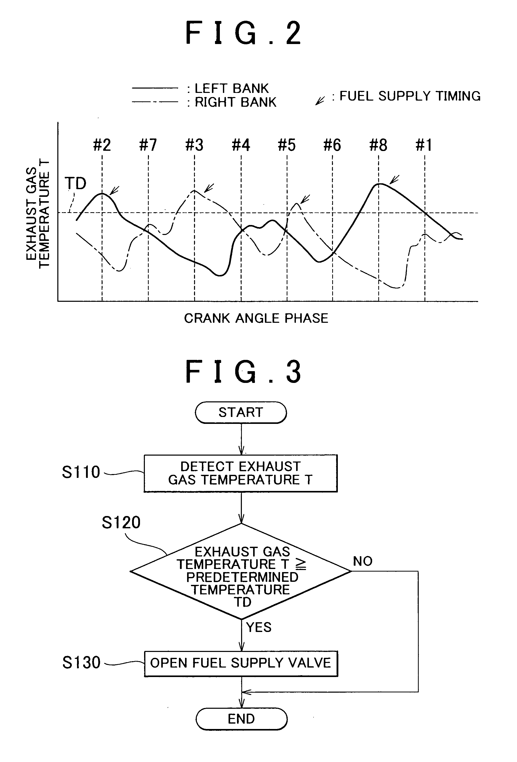
[0051] In the second embodiment, the fuel is supplied when the exhaust gas flow rate becomes local maximum. However, for example, in a case where each of the temperature sensors 74R and 74L is disposed at a distance from a position at which the fuel is supplied, the fuel supply timing may be set considering the flow of the exhaust gas. More specifically, a time interval may be provided between the timing at which the exhaust gas flow rate becomes local maximum, and the fuel supply timing.

[0052] More specifically, for example, in a case where the fuel supply valves 50R and 50L are provided at positions downstream of the temperature sensors 74R and 74L at a predetermined distance L from the temperature sensors 74R and 74L, respectively, and influence of the predetermined distance L is not negligible, it is preferable that the fuel supply timing should be set such that the fuel is supplied after the exhaust gas flow rate becomes local maximum. Also, in this case, it is preferable that ...


PUM

PropertyMeasurementUnit
flow rateaaaaaaaaaa
rotational speedaaaaaaaaaa
temperatureaaaaaaaaaa

Abstract

In an exhaust gas control apparatus and exhaust gas control method for an internal combustion engine, in which fuel is supplied to a purification mechanism provided in an exhaust passage so that a function of the purification mechanism is recovered. A flow rate of exhaust gas flowing in the exhaust passage or a value correlated with the flow rate is detected, and fuel supply timing is controlled based on a result of the detection. Accordingly, even when the flow rate of the exhaust gas flowing in the exhaust passage is variously changed based on the engine operating state, the fuel supply timing can be set based on the flow rate that is appropriately detected. Thus, it is possible to appropriately convey the supplied fuel to the purification mechanism using force of the exhaust gas.

Description

INCORPORATION BY REFERENCE [0001] The disclosure of Japanese Patent Application No. 2004-175941 filed on Jun. 14, 2004, including the specification, drawings and abstract is incorporate herein by reference in its entirety. BACKGROUND OF THE INVENTION [0002] 1. Field of the Invention [0003] The invention relates to an exhaust gas control apparatus and exhaust gas control method for an internal combustion engine, which includes a purification mechanism that purifies exhaust gas discharged from an internal combustion engine. [0004] 2. Description of the Related Art [0005] In general, an internal combustion engine is provided with an apparatus that purifies exhaust gas using a purification mechanism such as a catalyst. The purification mechanism is provided in an exhaust passage for the internal combustion engine. While the purification mechanism is used for a long time, particulate matter (PM) and sulfur components gradually adhere to the purification mechanism, and therefore a functio...

Claims


Application Information

Patent Timeline
Patent Type & Authority Applications(United States)
IPC IPC(8): B01D46/42F02D45/00B01D53/86F02F5/00F01N3/00F01N3/02F01N3/023F01N3/025F01N3/029F01N3/035F01N3/08F01N3/20F01N3/36F01N9/00F01N11/00F01N13/04F02B37/00F02B37/007F16J9/26
CPCF01N3/0253F01N3/035F01N3/0885F01N3/20F01N3/36F01N9/00F01N9/002F01N13/107F01N2250/02F01N2260/04F01N2570/04F01N2570/14F01N2610/03F01N2900/0422F02B37/00F02B37/007F02D41/1446Y02T10/47F01N13/011Y02T10/40
Inventor SUZUKI, HISANOBUTOYOTA, TADASHI
Owner TOYOTA JIDOSHA KK
Why Eureka
Try Eureka