Airbag inflator performance test system

Inactive Publication Date: 2005-12-15
HONDA MOTOR CO LTD
View PDF9 Cites 11 Cited by
  • Summary
  • Abstract
  • Description
  • Claims
  • Application Information

AI Technical Summary

Benefits of technology

[0008] The present invention has been accomplished under the above-mentioned circumstances, and it is an object thereof to provide an airbag i

Problems solved by technology

However, since the inflator generates gas by combustion of the propellant in a very short period of time, such as about 100 msec, there is no conventional test system that can accurately follow the way in which the energy of the gas generated by

Method used


Image

  • Airbag inflator performance test system
  • Airbag inflator performance test system
  • Airbag inflator performance test system

Examples


Embodiment Construction

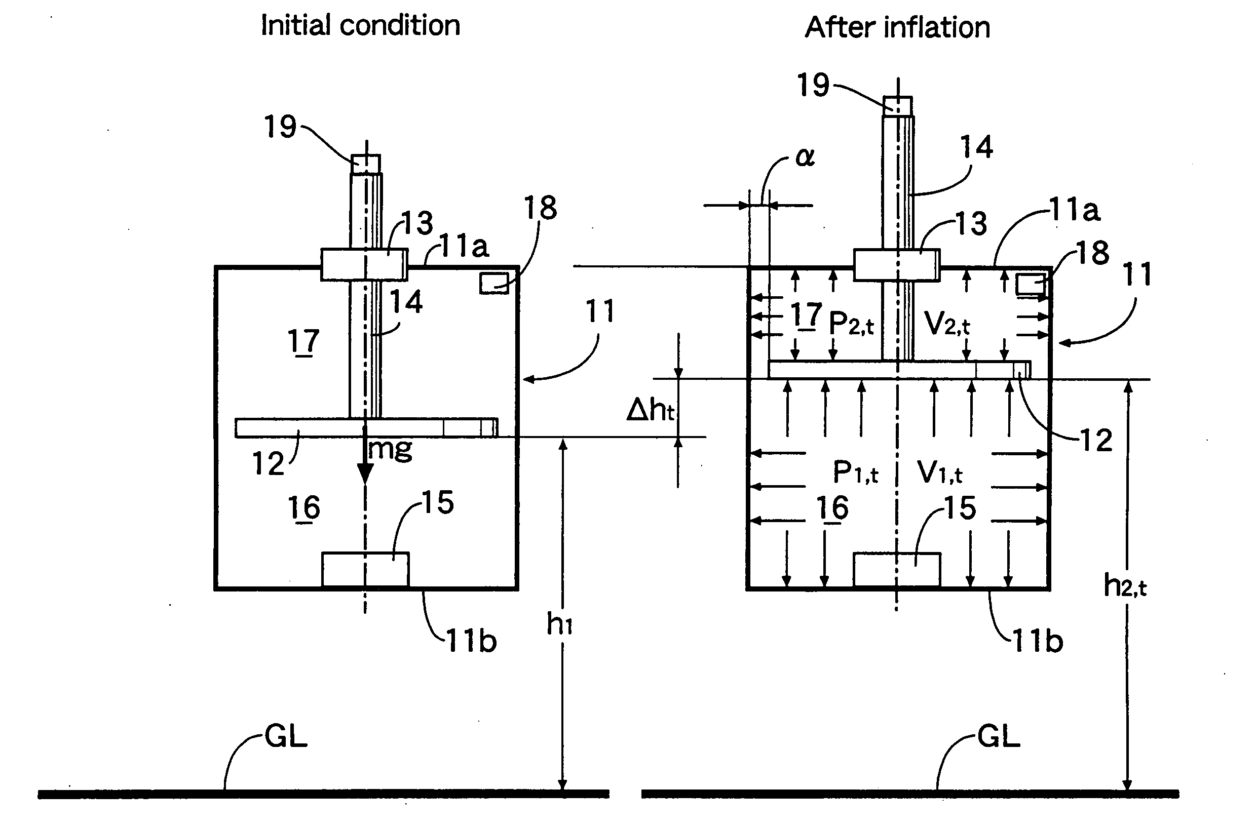
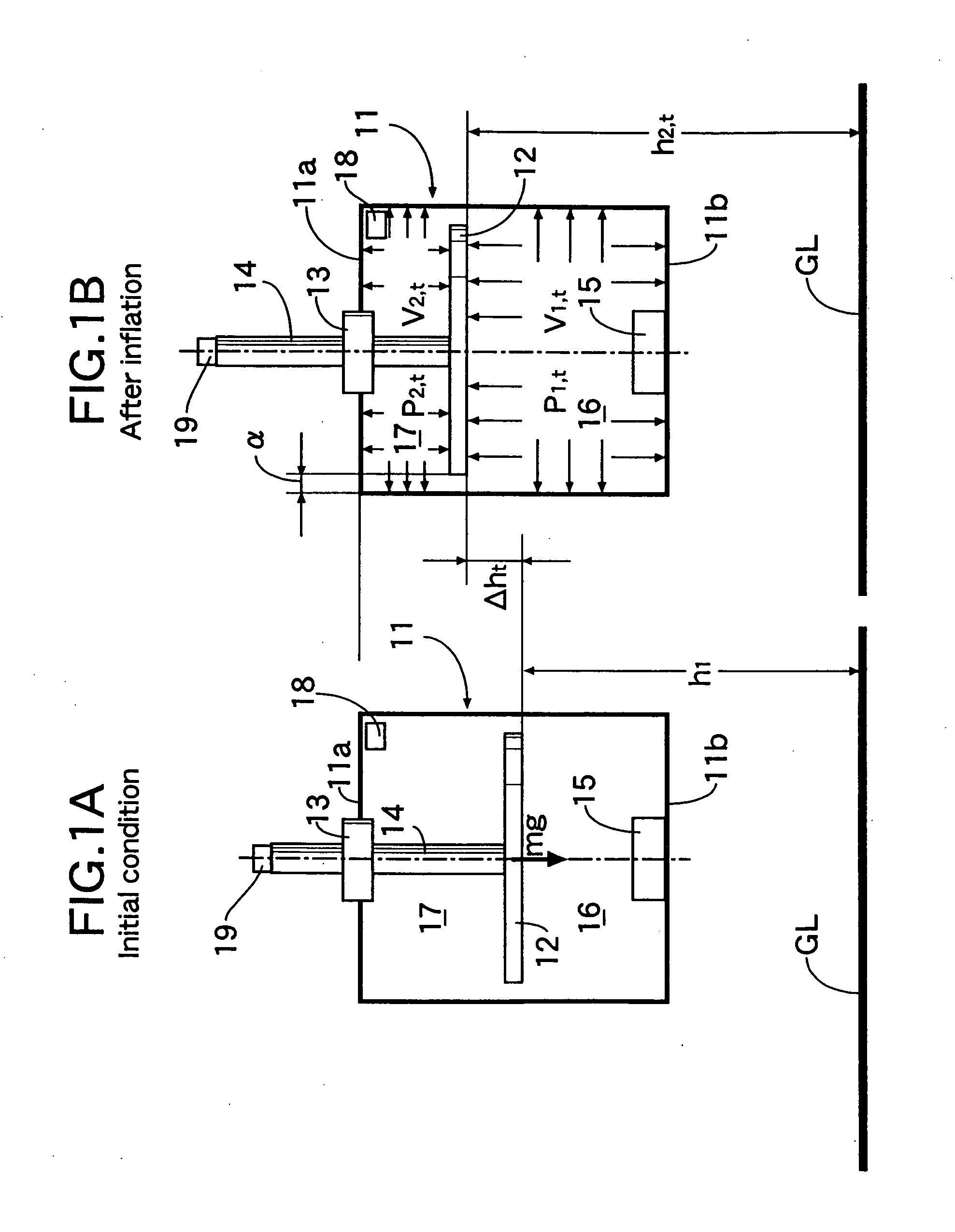
[0019]FIG. 1 shows a performance test system for testing the performance of an inflator that generates gas for deploying an airbag by combustion of a propellant. The system includes: a cylindrical tank 11 having upper and lower portions closed by an upper wall 11a and a lower wall 11b; a disk-shaped piston 12 vertically movably guided by the tank 11; and a piston rod 14 that projects upward from the center of the piston 12 and runs slidably through a bushing 13 that is provided in the upper wall 11a of the tank 11 and that has a low sliding resistance. The interior of the tank 11 is divided into a lower chamber 16 and an upper chamber 17 by the piston 12. An inflator 15 whose performance is to be tested is positioned at the center of the lower chamber 16. Furthermore, a small gap α is formed between the outer periphery of the piston 12 and the inner periphery of the tank 11, thus preventing sliding resistance from being generated between them and allowing gas to flow through the gap...


PUM


Abstract

An airbag inflator performance test system includes: a cylindrical tank; a disk-shaped piston vertically movably disposed with a gap between the piston and an inner peripheral face of the tank, the gap allowing gas to flow; a piston rod that projects upward from the piston and runs slidably through the tank so as to guide vertical movement of the piston; a lower chamber defined within the tank beneath the piston; an upper chamber defined within the tank above the piston; an inflator disposed in the lower chamber; a pressure sensor for detecting a pressure of the upper chamber; and a piston displacement sensor for detecting a displacement of the piston in order to detect a volume in the upper chamber. After ignition of the inflator, an inflator local work and an inflator total work, which are indexes of the energy of the inflator, are calculated based on the pressure and the volume of the upper chamber.

Description

RELATED APPLICATION DATA [0001] Japanese priority application No. 2004-175413, upon which the present application is based, is hereby incorporated in its entirety herein by reference. BACKGROUND OF THE INVENTION [0002] 1. Field of the Invention [0003] The present invention relates to a performance test system for an inflator that generates gas for deployment of an airbag for an automobile. [0004] 2. Description of the Related Art [0005] A method is known from Japanese Patent Publication No. 2613752 in which, taking into consideration the fact that a nitrate ester based explosive is degraded and decomposes to generate nitrogen oxides, the degree of degradation is determined by measuring the rate of generation of nitrogen oxides from a nitrate ester based explosive by means of a gas sensor device employing, as a sensing film, a phthalocyanine whose electrical resistance changes as a result of adsorption of the nitrogen oxides. [0006] Furthermore, a system is known from Japanese Patent...

Claims


Application Information

Patent Timeline
IPC IPC(8): G01M99/00B60R21/26G01N33/22
CPCB60R21/26G01M99/008
Inventor TONOOKA, DAIEIKAI, TAKESHIMORITA, YOSHIHIKO
Owner HONDA MOTOR CO LTD
Why Eureka
Try Eureka