[0014] In conventional CCFL designs, the CCFL is supported within the lighting device only at the two ends of the elongated lamp, so that the
mechanical integrity of the CCFL relies entirely on the mechanical strength of the elongated CCFL lamp itself . . . Therefore for
high intensity illumination applications where a long but narrow CCFL is employed, the CCFL becomes fragile and prone to damage. The
conventional technique of protecting the CCFL from the environmental forces by an outer shell impedes heat dissipation and reduces the efficiency and useful life of the lamp. For
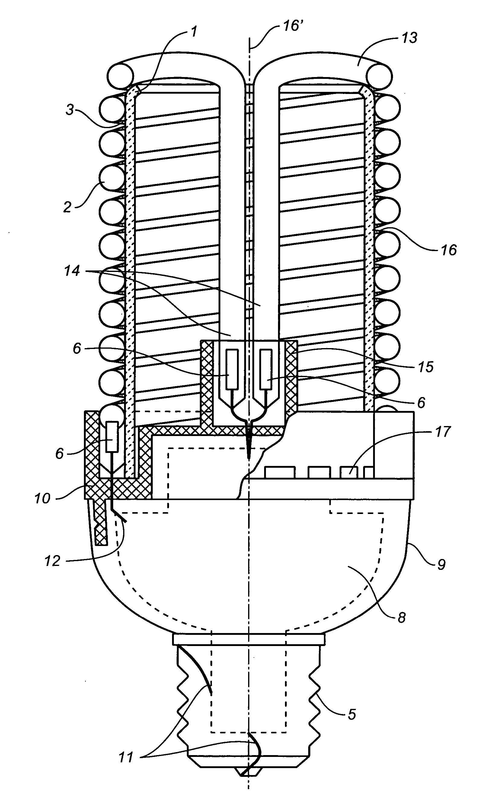
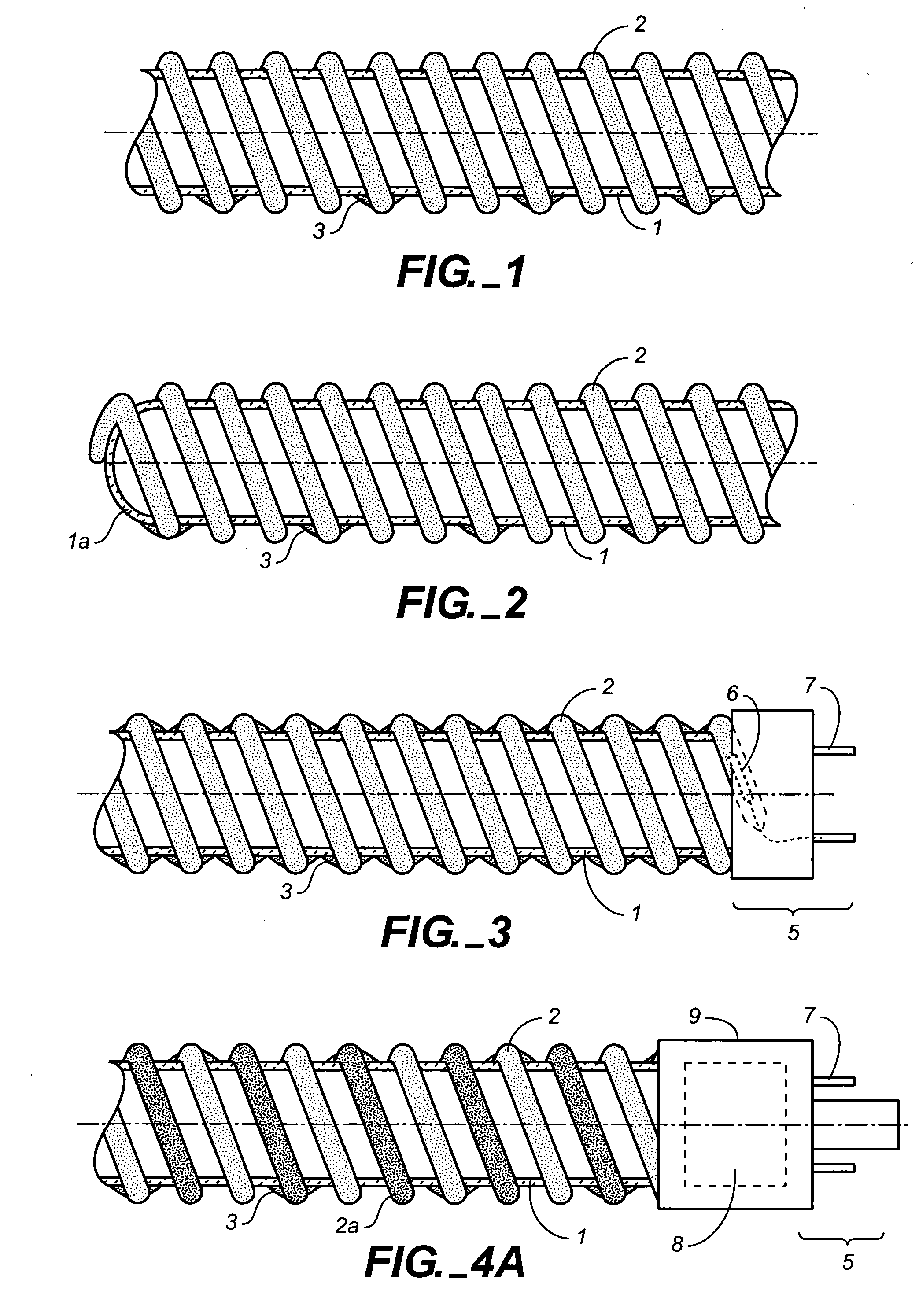
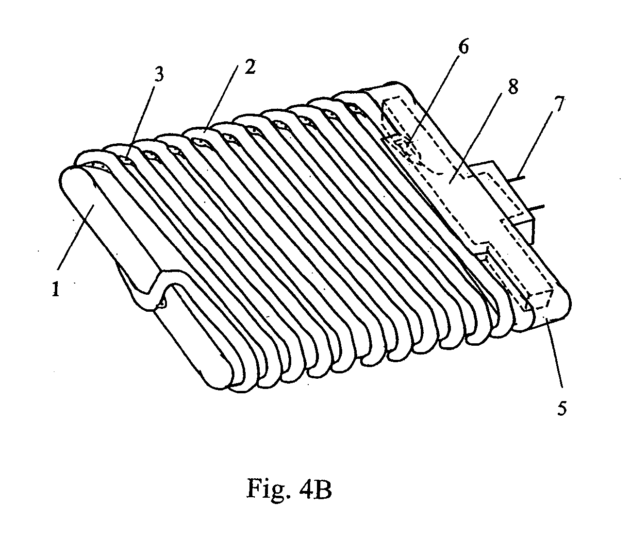
small form factor applications, a CCFL that is supported within the device only at its two ends may also be too fragile to be practical and too short to generate the required light output. One aspect of the invention is based on the recognition that by providing external support along the length of the elongated CCFL, so that the elongated CCFL is not relying on the support that it receives at its two ends, the above-described difficulties are overcome. This may be accomplished, in one embodiment, by attaching the elongated CCFL along its length at a plurality of locations to the surface of a lamp support, so that instead of relying only on the mechanic strength of the lamp itself, the elongated CCFL now finds mechanical support through the support member. By strengthening the
mechanical integrity in this manner, it is no longer necessary to protect the CCFL from the environment by the means of an outer shell or container, so that the heat generated by the CCFL may be readily dissipated. In this manner, the
operating temperature of the CCFL may be lowered compared to conventional designs so that it can operate within the optimal temperature range. Since the heat generated is readily dissipated, the driver for the CCFL would also not rise significantly so that its useful life is also increased compared to conventional designs.
[0015] By providing mechanical support to the CCFL as described above, it is also possible to provide a long but narrow CCFL that would fit within small form factor illumination applications, such as that of the MR-16 reflector lamp.
[0016] In conventional CCFL designs, the shape of the light source provided by the CCFL is determined only by the shape of the CCFL itself. However, since the mechanical strength of the conventional CCFL is determined only by that of the CCFL tube itself, because of the lack of mechanical strength, the shape of the light source that can be practically formed by the conventional CCFL is rather limited. By providing a lamp support attached to and supporting the light source along its length, the shape of the light source is no longer limited by what may be mechanically feasible for a
gas discharge lamp such as a CCFL without external support. It is therefore possible to provide a gas discharge light source with a wide variety of shapes compared to what is feasible with existing CCFL or HCFL devices.
[0017] A gas discharge device such as a CCFL is driven by a driver which is in turn connected to an outside power source such as a power outlet through an
electrical connector . . . The driver converts the power from the power outlet into appropriate
voltage and current for driving the gas discharge device such as a CCFL. To further increase the mechanical strength of the illumination device, according to another aspect of the invention, the above-described lamp support is mechanically connected to the
electrical connector either directly or through a housing for the driver to form a substantially
rigid structure, in an integral or unitary body.
[0018] In one embodiment, the CCFL is preferably in the shape of a spiral (e.g. single, double or multiple spirals or coils) which surrounds the lamp support. Also preferably, the lamp support is in the shape of a pole so that the CCFL wraps around the pole and is attached to the pole surface at a number of locations for increased mechanical strength.
[0019] The above described features may be used independently of one another or in any combination for various lighting applications. Compared to existing technology, the
high intensity illumination applications using one or more of the above-described features provide a gas discharge lighting device with high mechanical strength, and high light generating efficiency with long useful life. The device can withstand vibrations or shock and the driver is less affected by the heat generated by the lamp itself, since the device has good heat dissipation characteristics.

