
Comparator and method for amplifying an input signal

Inactive Publication Date: 2005-12-15
POLARIS INNOVATIONS
View PDF6 Cites 4 Cited by
  • Summary
  • Abstract
  • Description
  • Claims
  • Application Information

AI Technical Summary

Benefits of technology

[0017] Advantageously, the clamping capacitor is coupled to a resistor. The use of a resistor to locally bias the comparator might be preferred to the use of a transiator biased in the saturation region. Local bias minimizes performance uncertanities arising due to unstable bias and noise coupling on the bias line, which may need to be routed from a far away bias source.

Problems solved by technology

However, variations in process, voltage, temperature and variations in the above reference voltage (due to switching noise, dc drift, etc.) might lead to a relatively bad quality of the output signal, e.g., might have a negative impact on the small set-up and hold times, etc., etc.
Such effects are especially problematic, and are especially difficult to control when the interface signal changes its state with a relatively high frequency (e.g., 500 MHz and more).

Method used


Image

  • Comparator and method for amplifying an input signal
  • Comparator and method for amplifying an input signal
  • Comparator and method for amplifying an input signal

Examples


Embodiment Construction

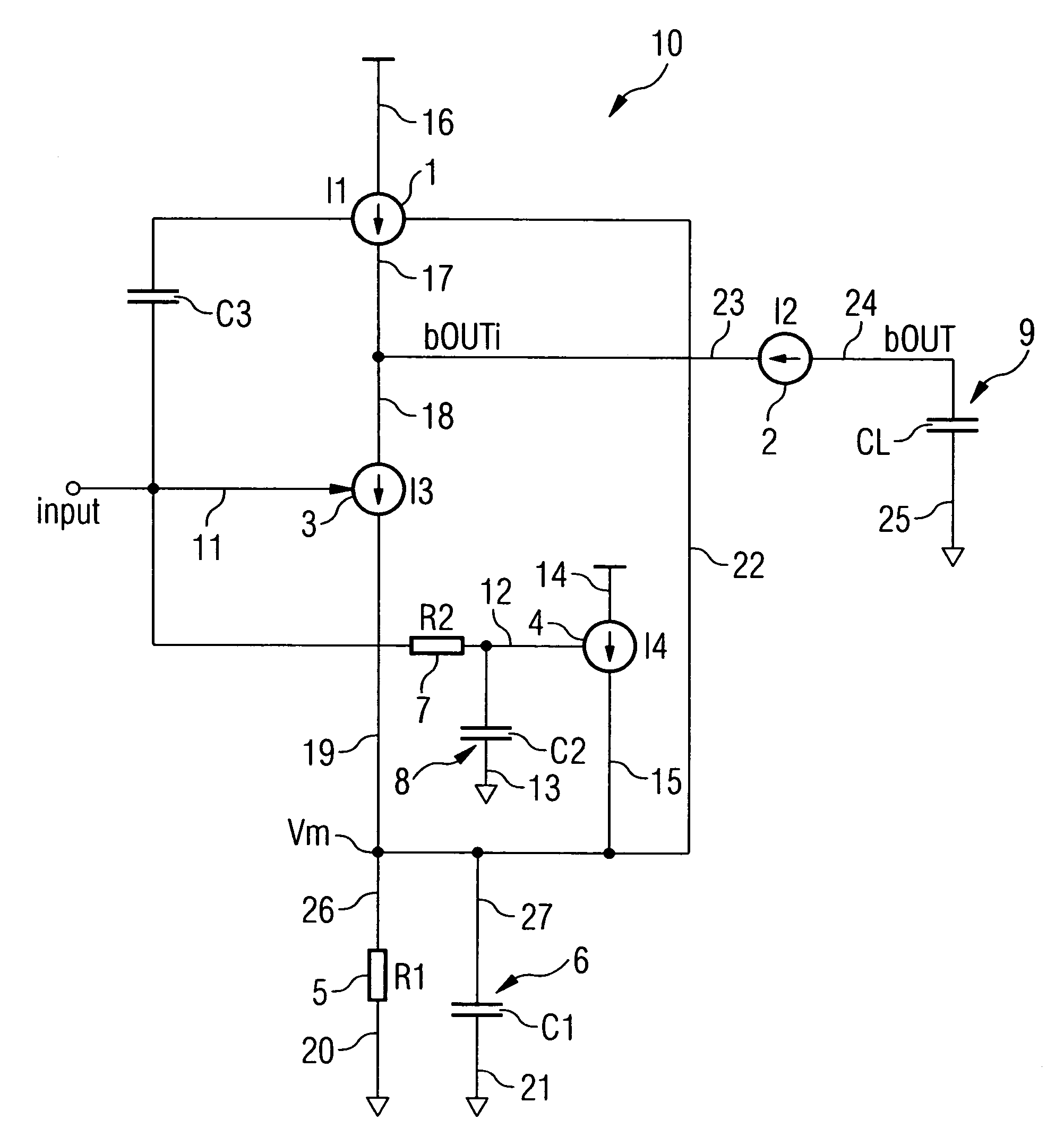
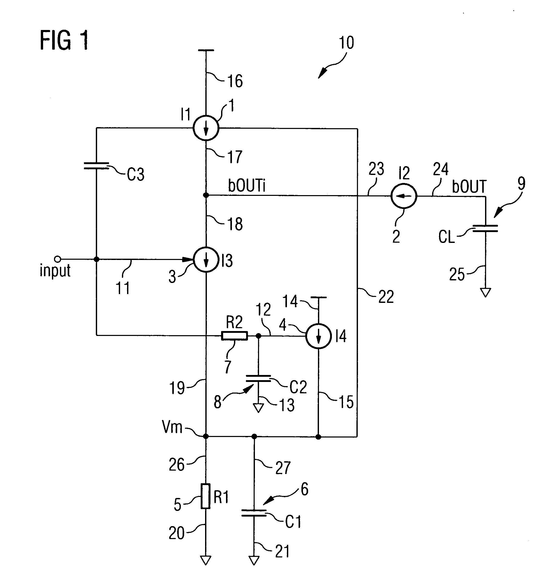
[0023] In FIG. 1, there is a block diagram representing an comparator according to an embodiment of the invention.

[0024] The comparator 10 may be used to amplify an interface signal input into an input (e.g., a respective pin) of a semiconductor chip, e.g., a memory chip, or a processor, etc., etc., or any other kind of (internal or external) signal input into the comparator 10 at an input line 11.

[0025] As is shown in FIG. 1, and as will be described in further detail below, the comparator according to the embodiment of the invention makes use of four different current sources / current sinks 1, 2, 3, 4, providing / sinking a current of I1, I2, I3 and I4, respectively.

[0026] The changes in the voltage level of the above input signal at the input line 11 might be relatively low.

[0027] The comparator 10 serves to amplify the input signal, and to output a respective, corresponding signal (more particular: an output signal bOUT inverse to the input signal) at an output line 24, which m...


PUM


Abstract

The invention refers to a comparator, and to a method for amplifying an input signal. The input signal is amplified by providing, by use of a first current source / sink, a first current to an output node, sinking, by use of a third current source / sink, a third current from the output node, and inputting the input signal to a control input of the third current source / sink, whereby a control input of the first current source / sink is connected to the third current source / sink by a clamping capacitor, such that an output node load capacitance, representing a second current source / sink, is rapidly charged when the input signal changes its state in a first direction, and is rapidly discharged when the input signal changes its state in a second direction.

Description

TECHNICAL FIELD OF THE INVENTION [0001] The invention refers to a comparator, and in particular, to a comparator for amplifying an interface signal at an input of a semiconductor chip, and to a method for amplifying an input signal without the aid of an explicit reference signal. BACKGROUND OF THE INVENTION [0002] In conventional semiconductor chips, e.g., respective memory chips, processors, etc., etc., for amplifying an interface signal at an input of the chip, a reference voltage is derived from a supply voltage (e.g. by the use of a voltage divider, and / or a diode, etc.). [0003] In conventional comparators, the level of the reference voltage or quiscent point might be compared with the voltage level of the interface signal at the input of the chip. The comparison circuit must detect and then amplify rail-to-rail voltage changes as set by specification. For example, in “High Type” terminated systems, the quiscent point or reference voltage is defined as 70% of the supply voltage ...

Claims


Application Information

Patent Timeline
IPC IPC(8): H03K5/24G01R31/3193H03K5/22H03K5/003
CPCG01R31/31932H03K5/003H03K5/2481
Inventor ACHARYA, PRAMOD
Owner POLARIS INNOVATIONS
Learn More