Method of calibrating an interferometer and method of manufacturing an optical element

a technology of interferometer and manufacturing method, which is applied in the direction of reflective surface testing, structural/machine measurement, instruments, etc., can solve the problems of insufficient accuracy of conventional methods of calibrating an interferometer using diffractive patterns in some applications, and the accuracy of determining the deviation of the surface shape from the target shape is limited, so as to achieve low line density, easy manufacturing, and high accuracy

Inactive Publication Date: 2005-12-15
CARL ZEISS SMT GMBH
View PDF11 Cites 25 Cited by
  • Summary
  • Abstract
  • Description
  • Claims
  • Application Information

AI Technical Summary

Benefits of technology

[0014] Further, embodiments of the present invention provide a method of testing and manufacturing an optical element having an aspherical surface of a relatively high accuracy.
[0020] A diffractive pattern having a lower line density may be easier to manufacture with a high accuracy than a diffractive pattern having a higher line density. Further, the effect of the diffractive pattern having the lower line density on the measuring light may be predicted with a higher precision than the effect of a diffractive pattern having a higher line density. For determining the effect of the diffractive pattern having the lower line density, calculations based on a scalar diffraction theory may be sufficient, whereas calculations based on rigorous diffraction theories may be necessary for determining the effect of the diffractive pattern having the higher line density.

Problems solved by technology

Herein, an accuracy with which the deviations of the surface shape from its target shape can be determined is limited by an accuracy with which the compensating system conforms with a specification thereof.
It has been found that the conventional methods of calibrating an interferometer using a diffractive pattern have an insufficient accuracy in some applications.

Method used


Image

  • Method of calibrating an interferometer and method of manufacturing an optical element
  • Method of calibrating an interferometer and method of manufacturing an optical element
  • Method of calibrating an interferometer and method of manufacturing an optical element

Examples


Embodiment Construction

[0041] In the exemplary embodiments described below, components that are alike in function and structure are designated as far as possible by alike reference numerals. Therefore, to understand the features of the individual components of a specific embodiment, the descriptions of other embodiments and of the summary of the invention should be referred to.

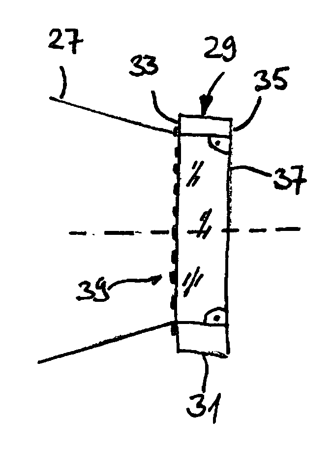
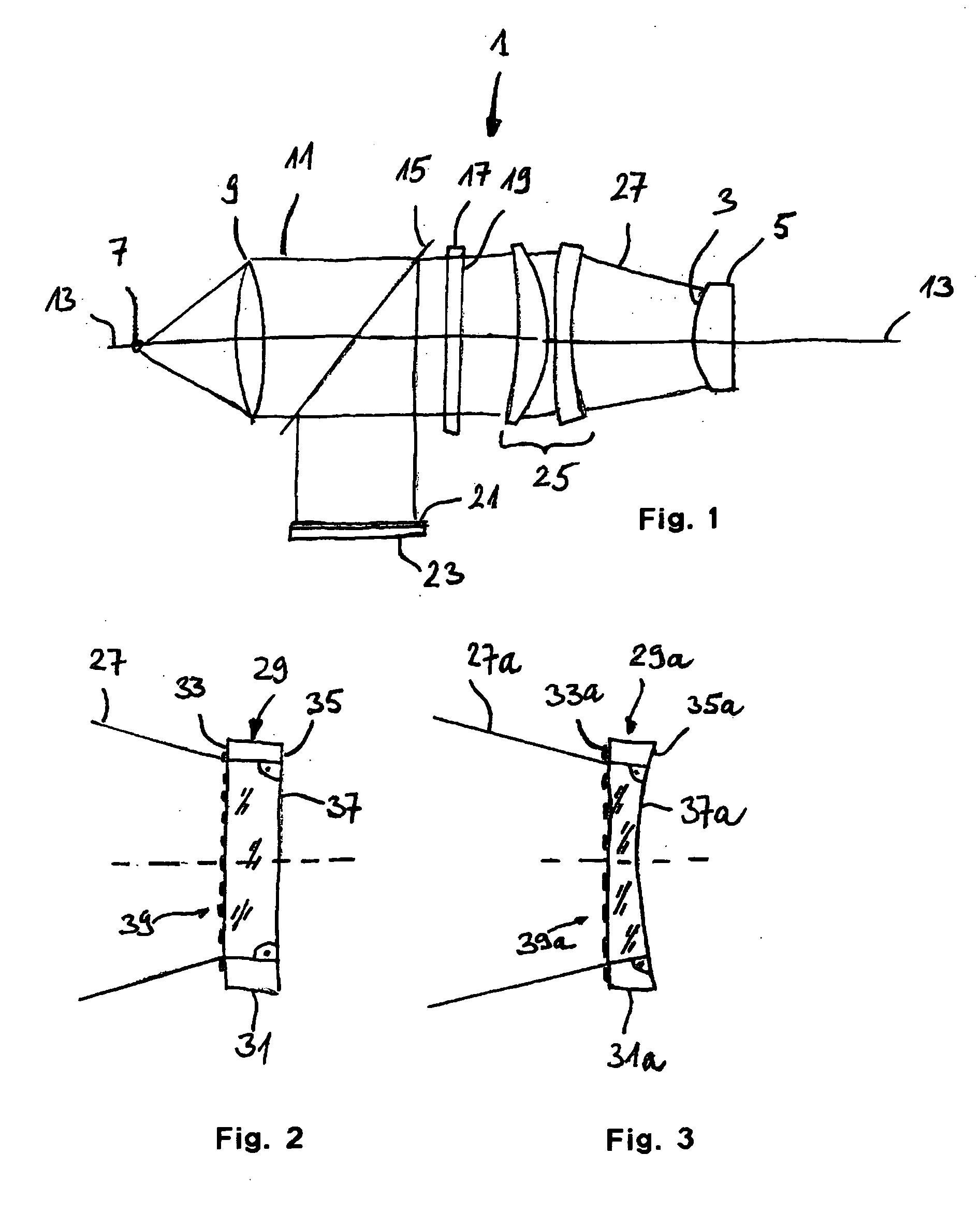
[0042] An interferometer system 1 schematically illustrated in FIG. 1 is used for testing an optical surface 3 of an optical component 5. The optical surface of the illustrated example has an aspherical surface shape. The Interferometer 1 of the illustrated example is of a Fizeau type and comprises a light source 7 emitting measuring light, The emitted light is formed to a parallel beam 11 by a collimation optics 9 such that wavefronts of the light of beam 11 are substantially flat wavefronts oriented orthogonal to an optical axis 13 of the interferometer 1. The wavefronts traverse a beam splitter 15 and a plate 17 having a surface...


PUM


Abstract

A method of calibrating an interferometer for determining an optical property of the interferometer uses a calibrating optical arrangement. The calibrating optical arrangement comprises at least one diffractive pattern and a mirror having a reflecting surface. The diffractive pattern and the reflecting surface are disposed at a distance from each other in a beam path of measuring light emitted from an interferometer optics of the interferometer system to be calibrated.

Description

[0001] This application is a continuation-in-part of International Application No. PCT / EP2002 / 013091 filed on Nov. 21, 2002, which International Application was not published by the International Bureau in English on Jun. 3, 2004, the entire contents of which are incorporated herein by reference. BACKGROUND OF THE INVENTION [0002] 1. Field of the Invention [0003] The present invention relates to the technical field of manufacturing optical elements and testing of optical elements using an interferometer. In particular, the present invention relates to a method of interferometric methods of objects having an aspherical surface. [0004] 2. Brief Description of Related Art [0005] The optical element is, for example, an optical lens or an optical mirror used in an optical system, such as a telescope used in astronomy and a projection optical system used for imaging structures, such as structures formed on a mask or reticle, onto a radiation sensitive substrate, such as a resist, in a lit...

Claims


Application Information

Patent Timeline
Patent Type & Authority Applications(United States)
IPC IPC(8): G01B9/02G01M11/00
CPCG01M11/005G01B9/02072G01B9/02039
Inventor FREIMANN, ROLFDOERBAND, BERNDSCHILLKE, FRANKBEDER, SUSANNESCHULTE, STEFAN
Owner CARL ZEISS SMT GMBH
Why Eureka
Try Eureka