
Traffic distribution control device

a control device and traffic technology, applied in the field of traffic distribution control technology, can solve the problems of inability to ensure and the inability to achieve qos for the overall bandwidth of the logical por

Inactive Publication Date: 2005-12-15
FUJITSU LTD
View PDF12 Cites 183 Cited by
  • Summary
  • Abstract
  • Description
  • Claims
  • Application Information

AI Technical Summary

Benefits of technology

[0023] The present invention has an object to provide a technology for allowing bandwidth distribution to be performed evenly (strictly speaking, substantially evenly) across a plurality of physical ports composing a logical port for link aggregation.
[0024] The present invention has another object to provide a technique for allowing packet discard to be performed when a contractor (user) breaches the limitation of a maximum usable bandwidth in order to accelerate bandwidth distribution to be performed evenly across a plurality of physical ports composing a logical port for link aggregation.
[0038] According to the present invention, even when bandwidth distribution for link aggregation exhibits an imbalance, a ratio (flow rate ratio) of bandwidths used by a plurality of physical ports is fed back to improve a bandwidth distribution ratio, so that traffic distribution for the link aggregation can be performed evenly. Accordingly, the total sum of the bandwidths of the plurality of physical ports can be provided, and hence significant bandwidth resources of a carrier network can be effectively used.
[0039] Further, according to the present invention, even if the total flow rate for the link aggregation exceeds a maximum usable bandwidth, the physical ports configuring the link aggregation can be subjected to packet discard in descending order from the highest flow rate thereof to achieve even output flow rates, and the influence on traffic already in communication can be suppressed to a minimum. Accordingly, a communication carrier can provide a highly reliable wide-area LAN service.

Problems solved by technology

Then, the packet flow rates exhibit an imbalance, which causes a problem in that the packets concentrate on the physical port P1.
Meanwhile, control of bandwidth assurance (QoS: Quality of Service) in the link aggregation is performed on each of the physical ports composing the logical port, which leaves a problem in that the QoS is not assured for the overall bandwidth of the logical port.
Even though cell discard is controlled according to comparison results, the cell discard may still fall behind, and the total sum of the number of cells that have reached the virtual path bundle may breach the contract of a maximum usable bandwidth.
(1) Even if the link aggregation is configured for a layer 2 switch device by bundling a plurality of physical ports, the bandwidth cannot be distributed evenly across the physical ports, so that the total sum of bandwidths of the plurality of physical ports cannot be provided.
Therefore, significant bandwidth resources of a carrier network cannot be effectively used.
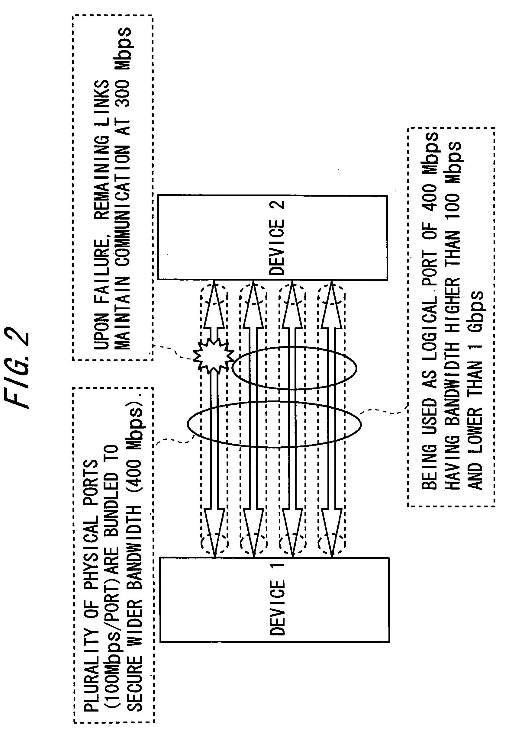
For example, even if 4 physical ports for 100 Mbps Fast Ethernet (Ethernet: registered trademark) are bundled into one to provide a user with a logical port for 400 Mbps, the bandwidth cannot actually be distributed evenly across the plurality of physical ports due to unbalanced traffic, so that the bandwidth of 400 Mbps cannot be secured.
(2) Even if the link aggregation is set for a layer 2 switch device, QoS is assured on a physical port (virtual path) basis, so that significant bandwidth resources of a carrier network are wasted.
However, the document does not make a proposal for packet discard to be performed when a contractor breaches the limitation of a maximum usable bandwidth.
Therefore, if the traffic exceeds the maximum usable bandwidth for the link aggregation, communication within a QoS bandwidth cannot be assured.
Accordingly, the communication carrier cannot provide a highly reliable wide-area LAN service.

Method used


Image

  • Traffic distribution control device
  • Traffic distribution control device
  • Traffic distribution control device

Examples


modified examples

[0214] The process according to the embodiment described above may be provided as a program executable by a computer, and may be provided by means of a recording medium such as a CD-ROM or a flexible disk or even through a communication line.

[0215] In addition, according to the embodiment described above, an arbitrary number or all of the processes may also be combined for execution. For example, the processes may be executed by combining the first and second operational modes with the third and fourth operational modes. In that case, after the process of the discard in the third and fourth operational modes with a high priority is performed, the process of equalized distribution in the first and second operational modes is executed. In consideration for the traffic inputted in the physical ports, which varies as time elapses, there is an advantage of facilitating the more equalized distribution.


PUM


Abstract

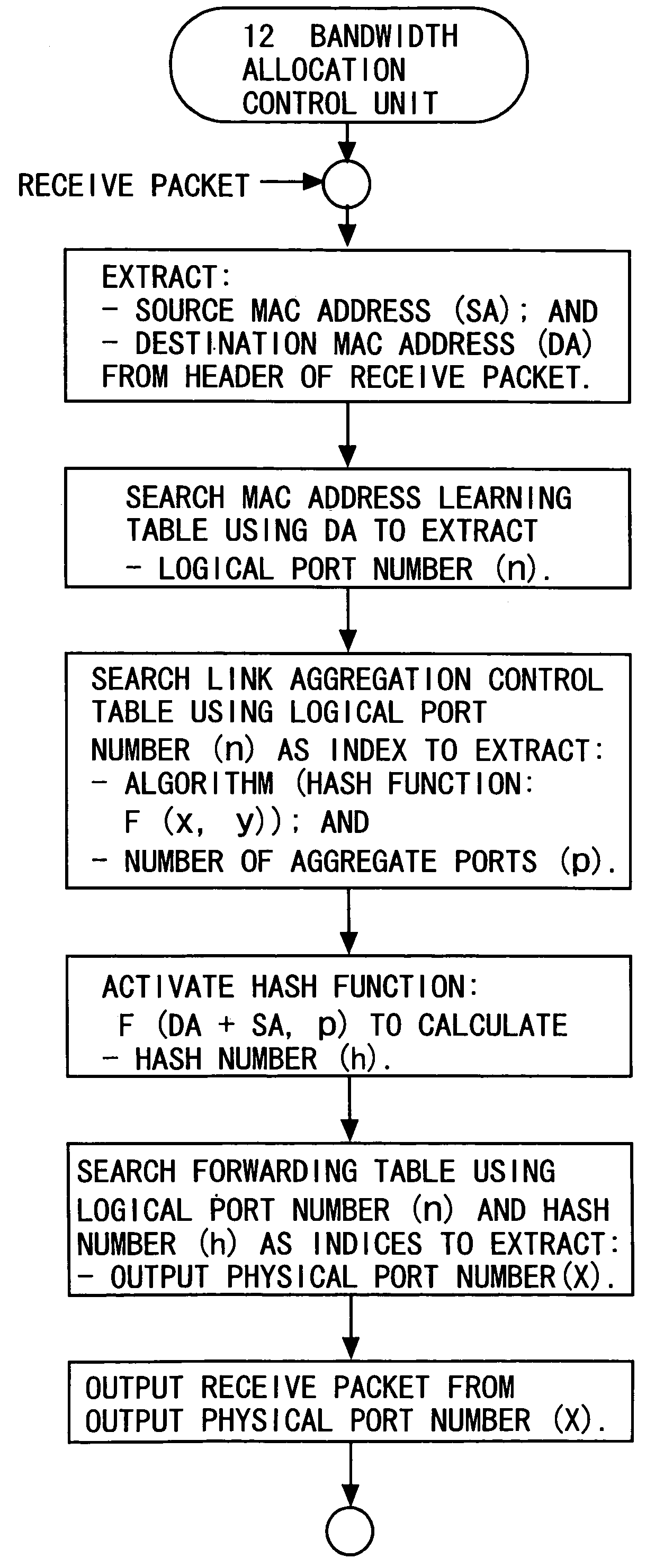
A data transmission device 10 serving as a traffic distribution control device is a device which, in order to distribute traffic across a plurality of physical ports composing a logical port for link aggregation, uses a hash function to calculate a hash value from a destination address and a source address of a receive packet, and determines a destination physical port. The traffic distribution control device includes a measuring unit 13 that measures an output flow rate of a packet outputted from each of the plurality of physical ports; a calculating unit 14 that calculates a flow rate ratio between the plurality of physical ports with respect to the measured output flow rates; and a first control unit 12 that feeds the calculated flow rate ratio back to a bandwidth distribution ratio between the plurality of physical ports to change numerical allocation of hash values for determining the destination physical port.

Description

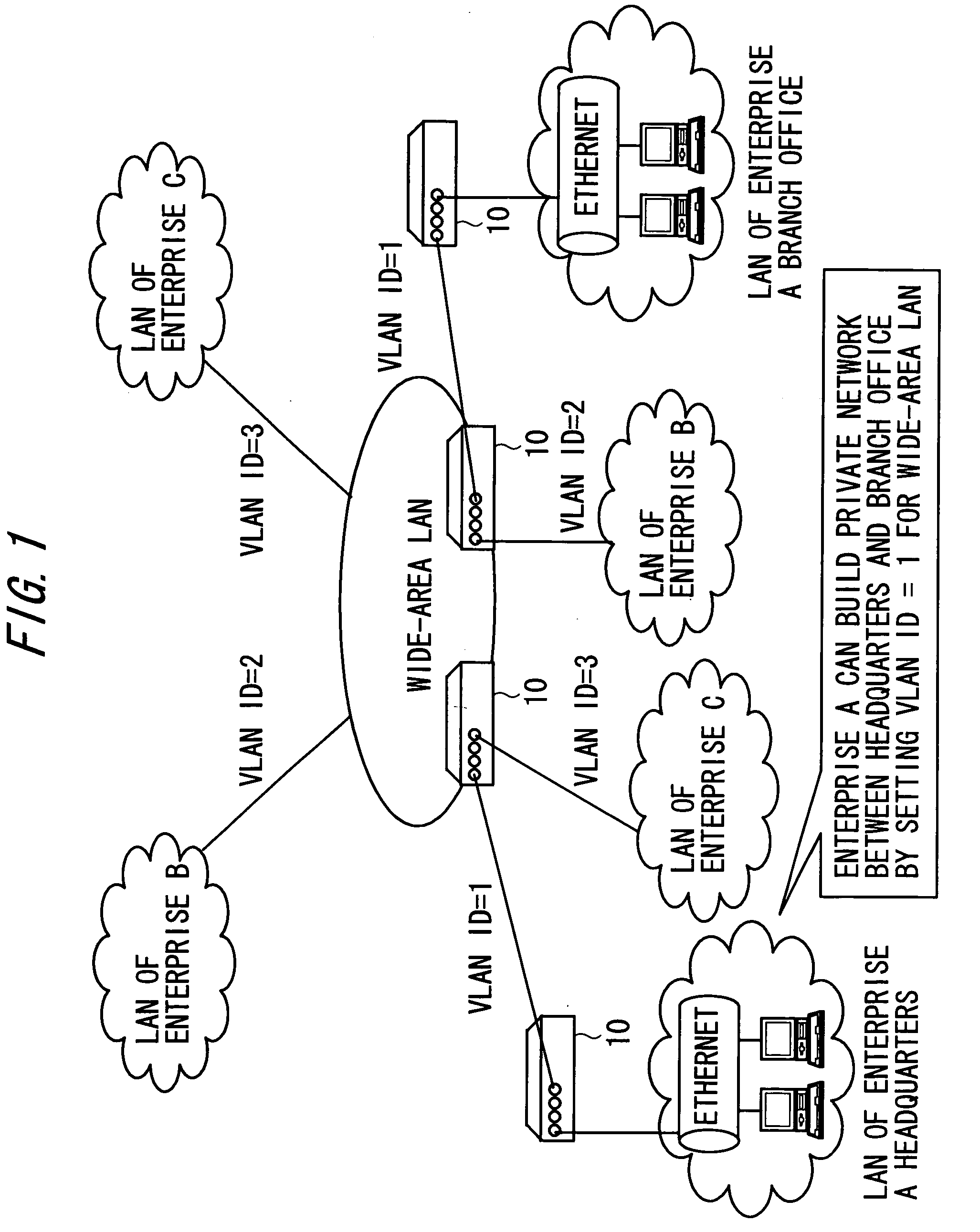
BACKGROUND OF THE INVENTION [0001] The present invention relates to a traffic distribution control technology for link aggregation used in a data transmission device for a communication carrier (communication provider) that provides a wide-area LAN (Local Area Network) service etc. or another such device. [0002] In the case of building a private network that allows an enterprise to connect multiple nodes, there are generally adopted a method of building a private network by using a dedicated line, a method of building a private network by an IP-VPN (Virtual Private Network) using an IP (Internet Protocol), and a method of building a private network by a wide-area LAN service using a VLAN (Virtual Local Area Network). [0003] Among those building methods, the method by the wide-area LAN service, which allows the building with a layer 2 switch device, requires lower cost and easier management than the method by using the dedicated line or the method by the IP-VPN, thereby showing a sig...

Claims


Application Information

Patent Timeline
Patent Type & Authority Applications(United States)
IPC IPC(8): H04L45/24H04J1/16H04J3/14H04L1/00H04L12/28H04L47/41
CPCH04L45/24H04L45/745H04L2012/5624H04L47/125H04L47/10
Inventor SUETSUGU, TAKAHIROKINOSHITA, HIROSHIYOSHIMI, MAKOTO
Owner FUJITSU LTD
Learn More