Gear pump

a gear pump and gear technology, applied in the field of gear pumps, can solve the problems of a number of performance limitations and significant limitations, and achieve the effects of reducing vibration, reducing turbulence, and reducing performan

Inactive Publication Date: 2005-12-15
M&M TECH
View PDF10 Cites 17 Cited by
  • Summary
  • Abstract
  • Description
  • Claims
  • Application Information

AI Technical Summary

Benefits of technology

[0008] In one embodiment having, certain features and advantages according to the present invention, a gear pump is configured to address the tendency of conventional gear pumps to show significant reductions in performance as the teeth experience wear. In such an embodiment, the gear pump may utilize a modified gear tooth profile

Problems solved by technology

Such conventional gear pumps are simple and relatively inexpensive, but suffer from a number of performance limitations.
This type o

Method used


Image

  • Gear pump
  • Gear pump
  • Gear pump

Examples


Embodiment Construction

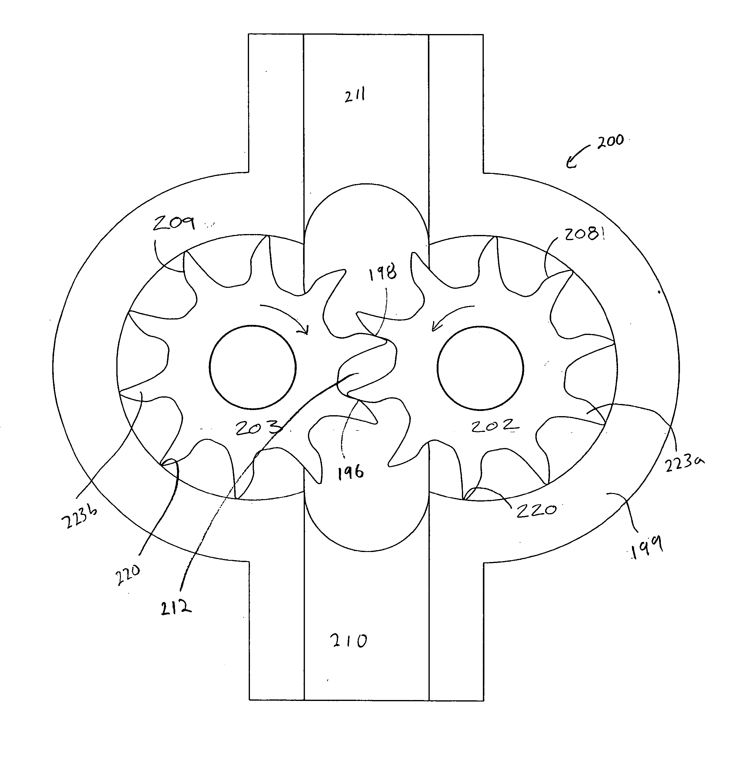
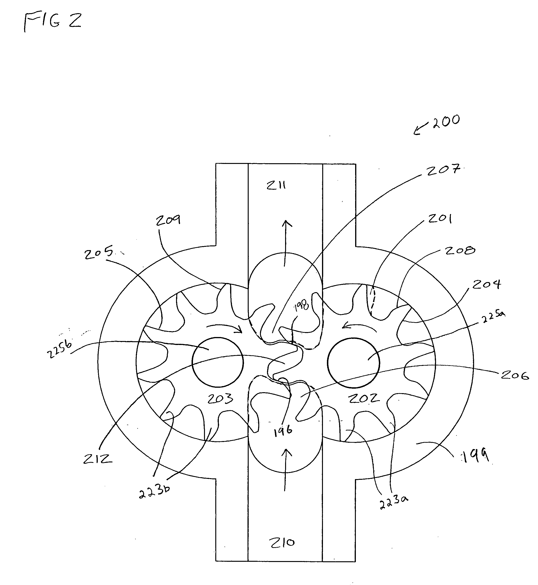
[0059]FIGS. 2-5 illustrate an exemplary embodiment of an internal gear pump 200 having certain features and advantages according to the present invention. The term “pump” is used broadly, and includes its ordinary meaning, and further includes a device which displaces fluid or which turns as the result of the displacement of fluid, either compressible or incompressible. As such, he term “pump” is intended to include such applications as hydraulic motors or other devices which require expanding chambers or compressing chambers or both. In addition, throughout this description reference is made to certain directions (e.g., forward, backward, up, down, etc.) and relative positions (e.g., top, bottom, lower, upper, side, etc.). However, it should be appreciated that such directions and relative positions are intended merely to help the reader and are not intended to limit the invention.

[0060] The exemplary pump 200 comprises a casing 199 and a pair of opposing rotors 202, 203, with int...


PUM


Abstract

A pump comprises a driving rotor and a driven rotor that are positioned in a housing such that, as the driving rotor and the driven rotor rotate, the teeth of the driving rotor and the teeth of the driven rotor mesh to form a positive displacement seal. The teeth of the driving rotor and the driven rotor are configured such that seals between the inlet side and the discharge side of the pump are formed between only the leading surfaces of the teeth of the driving rotor and the trailing surfaces of the teeth of the driven rotor.

Description

PRIORITY INFORMATION [0001] This application claims priority under 35 U.S.C. § 119(e) of Provisional Application 60 / 385,689, filed Jun. 3, 2002 and Provisional Application 60 / 464,395 filed Apr. 18, 2003, the entirety of these applications are herein incorporated by reference.BACKGROUND OF THE INVENTION [0002] 1. Field of the Invention [0003] The present invention relates to pumps, and, in particular, to gear pumps. [0004] 2. Description of the Related Art [0005]FIG. 1 is a schematic illustration of an exemplary prior art gear pump 100. Such a pump 100 typically includes a casing 111 and a pair of rotors 113, 115, with intermeshing gear teeth 117. The casing 111 defines an inlet port 107 and an outlet port 108, which extend in a generally radial direction with respect to the rotors 113, 115. Fluid is carried from the inlet port 108 in spaces (or chambers) 102 that are formed between the gear teeth of the rotors. The fluid in these chambers 102 is displaced as the teeth engage with th...

Claims


Application Information

Patent Timeline
IPC IPC(8): F01C1/18F03C2/00F03C4/00F04C2/00F04C2/08F04C2/10F04C2/18F04C2/20F04C11/00F04C18/00
CPCF04C2/084F04C2/101F04C11/001F04C2/18F04C2/20F04C2/102
Inventor KLASSEN, JAMES B.
Owner M&M TECH
Why Eureka
Try Eureka