Photovoltaic module with at least one crystalline solar cell

a technology of photovoltaic modules and solar cells, applied in the direction of photovoltaic energy generation, basic electric elements, electrical apparatus, etc., can solve the problems of solar cells that cannot be re-assembled, individual solar cells or modules fail, and approximately 30% of the cost of the process arises, so as to improve the mechanical and chemical properties, improve the effect of optical, mechanical and chemical properties

Inactive Publication Date: 2009-12-17
SITEC SOLAR
View PDF6 Cites 0 Cited by
  • Summary
  • Abstract
  • Description
  • Claims
  • Application Information

AI Technical Summary

Benefits of technology

[0011]The object of the invention is to provide a photovoltaic module comprising at least one crystalline solar cell, in which the optical, mechanical and chemical properties are improved and the production is fast, inexpensive and capable of being highly automated.

Problems solved by technology

In particular, permeability to water vapour is a problem for solar cells.
Corrosion of the metal contacts (current collectors) leads to the failure of individual solar cells or to the failure of the module, since the solar cells are connected in series.
Approximately 30% of the costs arise from the process of producing the photovoltaic modules comprising crystalline solar cells from the individual components.
These costs are caused by the high proportion of production steps that cannot be automated, and by long process times during lamination of the end product.
During this time, the production machine is occupied and cannot be used for any further product.
A continuous production process is not possible.
A further disadvantage of EVA is that it does not possess long-term UV resistance.
As a result, a drop in performance of the module will also be seen.
The other proposed materials also have this problem.
However, this only slows down the ageing process.
A further disadvantage of all the described encapsulating materials is that they are plastics.
EVA solves this problem only to an insufficient extent.
A number of undesirable effects arise in the process, for example the displacement of the crystalline solar cells in the laminator, the escape of material at the module edges, a non-uniform layer structure in height terms, and the incorporation of mechanical stresses at the solar cell connectors.
This laminating process causes high process times and thus high costs, is difficult to automate, and faulty laminates can no longer be repaired.
A further disadvantage of this technology is the rear-side structure of the photovoltaic module.
However, plastics have the property of being poor heat conductors.
The heat dissipation from the solar cell is completely insufficient.

Method used


Image

  • Photovoltaic module with at least one crystalline solar cell
  • Photovoltaic module with at least one crystalline solar cell

Examples


Embodiment Construction

OF EMBODIMENTS OF THE INVENTION

[0032]The invention will be explained in more detail below on the basis of examples of embodiments and with reference to the figures of a drawing, in which:

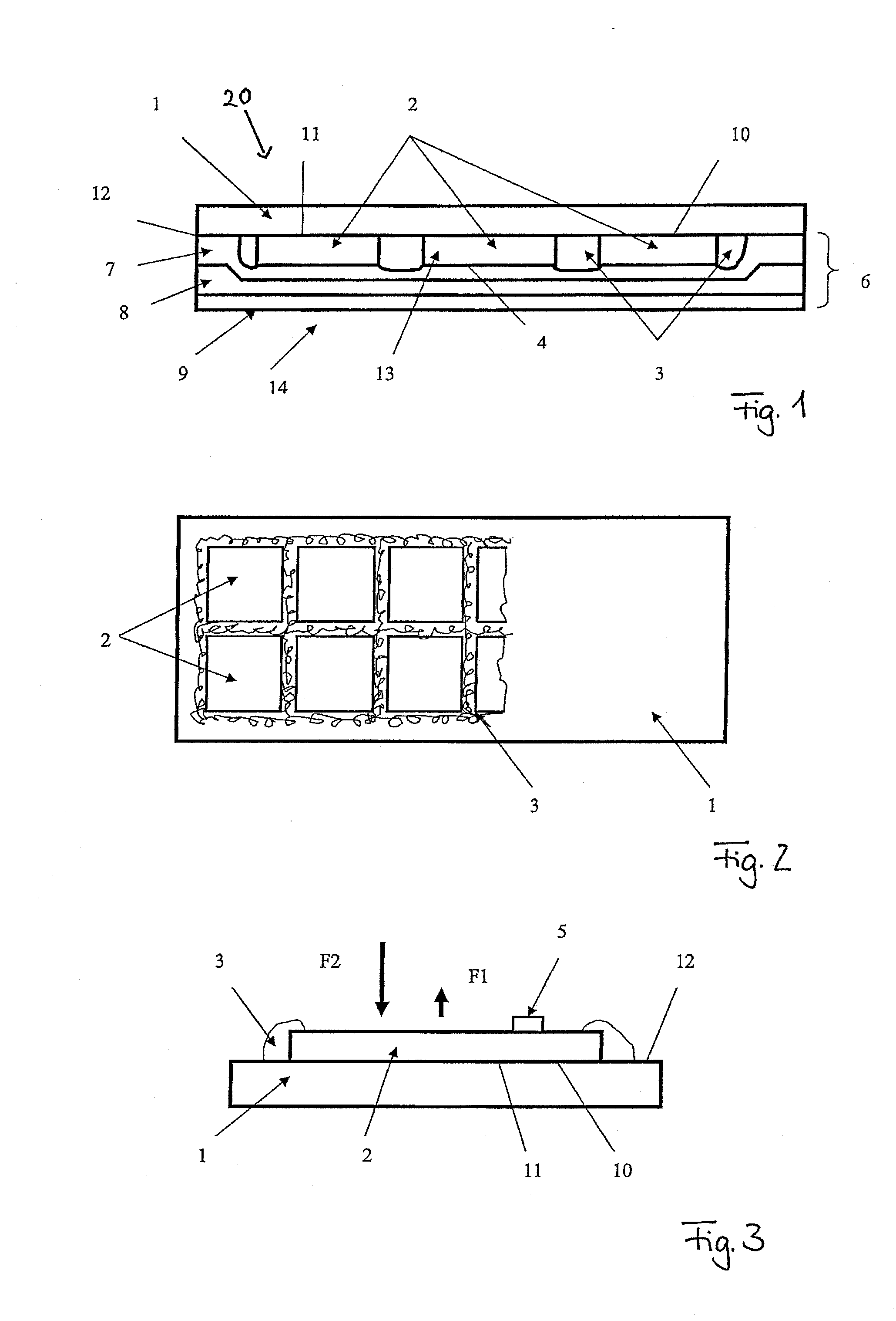
[0033]FIG. 1 shows, from above, an arrangement comprising a carrier substrate for a photovoltaic module and a plurality of crystalline solar cells arranged thereon;

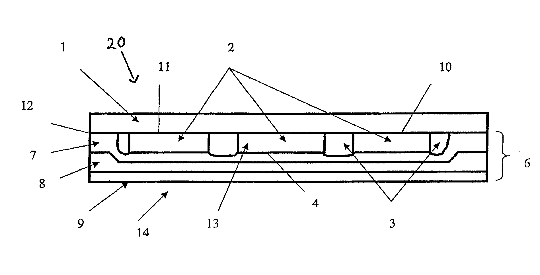
[0034]FIG. 2 shows, in cross section, a detail of the arrangement of FIG. 1; and

[0035]FIG. 3 shows, in cross section, a photovoltaic module using the arrangement of FIG. 1.

[0036]FIG. 1 shows, from above, an arrangement comprising a carrier substrate 1 for a photovoltaic module 20 and a plurality of solar cells 2 arranged thereon and of a so-called crystalline type. The solar cells 2, which comprise a crystalline photoactive material, are arranged flat next to one another at a small distance of approximately 2 to 3 mm. Once the solar cells 2 have been positioned, a respective edge seal 3 is applied around the solar cells 2. With this struc...


PUM


Abstract

The invention relates to a photovoltaic module, in which at least one crystalline solar cell, by means of which light energy can be converted into electrical energy, is arranged on a carrier substrate, characterized in that a contact area is formed between the carrier substrate and the at least one crystalline solar cell, wherein, in the region of the contact area, an outer surface on a light entry side of the at least one crystalline solar cell is in contact with a rear surface of the carrier substrate, and in that electrical connection contacts are arranged on the rear side of the at least one crystalline solar cell facing away from the light entry side.

Description

[0001]The invention relates to a photovoltaic module comprising at least one crystalline solar cell.BACKGROUND OF THE INVENTION[0002]A photovoltaic module or solar module serves for directly generating electrical power from sunlight. This technical device consists of a composite system comprising a plurality of components. It is possible to distinguish between on the one hand photovoltaic modules comprising amorphous solar cells, and on the other hand photovoltaic modules in which a previously produced crystalline solar cell is arranged on a carrier substrate. In the photovoltaic modules comprising amorphous solar cells, as used for example in the document DE 40 26 165 C2, the solar cells are deposited step-by-step on a carrier substrate, for example by means of thin-layer technology, in order thus to create the layer structure which performs the energy conversion. The carrier substrate, for example glass, then forms in practice an inherent and necessary component of the amorphous s...

Claims


Application Information

Patent Timeline
Patent Type & Authority Applications(United States)
IPC IPC(8): H01L31/00
CPCH01L31/02167Y02E10/50H01L31/048
Inventor ALBRECHT, DIRK
Owner SITEC SOLAR
Why Eureka
Try Eureka