Wrench for use in limited access areas

a limited access and wrench technology, applied in the direction of wrenches, screwdrivers, manufacturing tools, etc., can solve the problems of ratchet wrenches described above being subject to breakage, unable to provide enough space, and unable to meet the needs of use,

Inactive Publication Date: 2005-12-22
RICHTER MILTON
View PDF5 Cites 9 Cited by
  • Summary
  • Abstract
  • Description
  • Claims
  • Application Information

AI Technical Summary

Benefits of technology

[0009] The instant invention may provide a socket wrench for use in tight areas where there is limited access or a very small turning arc or both. The wrench may have two basic components and no moving parts. The wrench may not be damaged under the stress of normal use and may be used with nuts and bolts of various shapes. Accommodations may be made for nuts and bolts of different sizes.

Problems solved by technology

In many instances the location of the nut or bolt does not provide enough space to permit the use of such wrenches.
Wrenches with ratchet mechanisms are also well known, but are subject to breakage under excessive forces and can usually be rotated in only one direction.
This wrench can be use to both tighten and loosen a nut or bolt and uses a small turning arc, but the mechanism can be subject to breakage under pressure.
The ratchet wrenches described above are subject to breakage under large forces while many of the other wrenches are made for specific uses and are not practical for general usage.

Method used


Image

  • Wrench for use in limited access areas
  • Wrench for use in limited access areas
  • Wrench for use in limited access areas

Examples


first embodiment

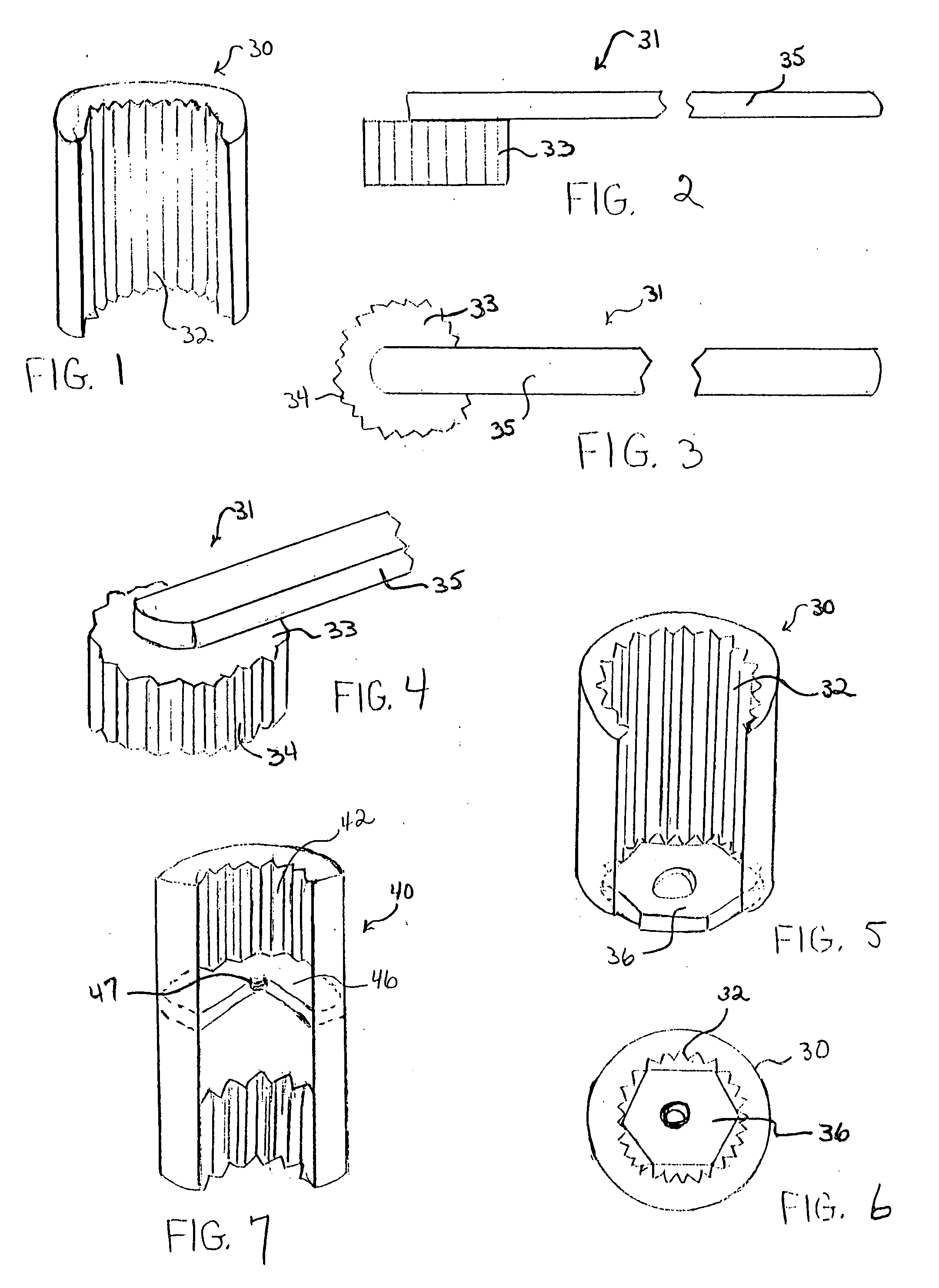
[0049] the instant invention may consist of two parts, the socket 30 and the handle assembly 31. The socket 30, seen in FIGS. 1 and 5, may be a hollow cylinder that may have axially fluted interior walls. The fluting 32 may provide a good grip on nuts and bolts having different shapes, i.e., square or hexagonal. An example of a hexagonal nut 36 within the socket 30 may be seen in FIGS. 5 and 6. The handle assembly 31 may have a solid cylindrical head 33 with fluting 34 on its outer surface which may cooperate with and complement the fluting 32 of the interior of the socket 30. The head 33 may be attached to one end of a shaft 35. The shaft 35 may be affixed to the head 33 by welding or other means known in the art. The head 33 and shaft 35 may also be of singular construction. See FIGS. 2, 3 and 4. The head 33 may be inserted into the top of the socket 30 to form a socket wrench.

[0050] To use the wrench the socket 30 may be placed over the nut 36 or bolt (not shown) and the head 33 ...

second embodiment

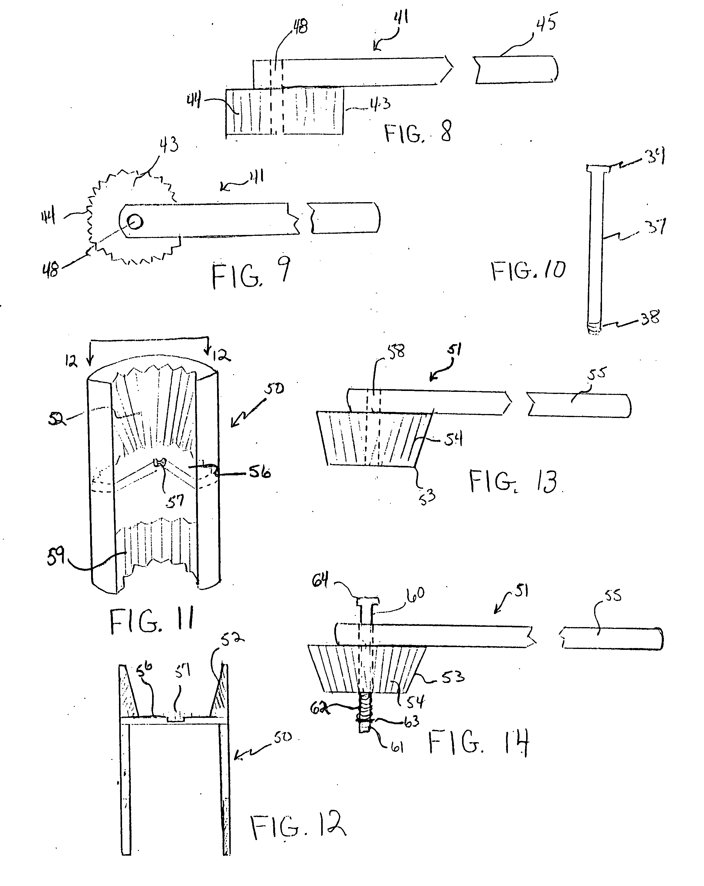
[0051] the instant invention may also consist of a hollow cylindrical socket 40 and handle assembly 41. Referring to FIG. 7, the socket 40 may be divided into two interior compartments, an upper compartment and a lower compartment, by means of a transverse partition 46. The interior walls of both compartments may be fluted. The fluting 42 of the upper compartment may have the same tooth size and arrangement as in the lower compartment, or it may be different, according to usage and method of manufacture. There may be a depression or opening 47 with threaded walls centrally located on the upper surface of the partition 46. Alternatively, a threaded nut or small cylinder (not illustrated) may be welded to the center of the partition. The handle assembly 41 may also consist of a solid cylindrical head 43 with a fluted 44 outer surface and a shaft 45. There may be a smooth bore 48 through the end of the shaft 45 and extending through the center of the head 43. FIGS. 8 and 9.

[0052] A pin...

third embodiment

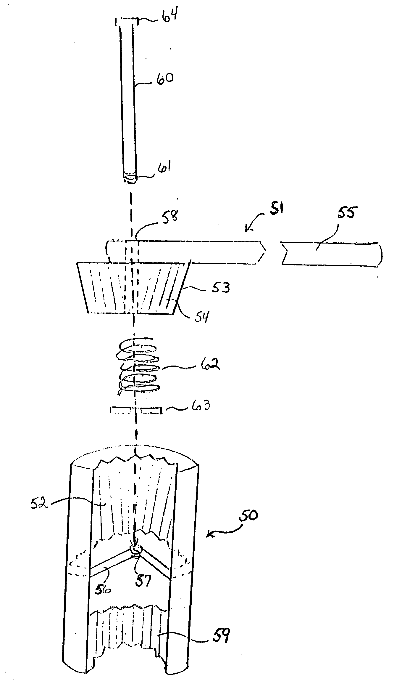
[0055] A small turning arc A may be seen in FIG. 16, while a larger turning arc B is illustrated in FIG. 17. When the straight sided socket 40 is used, the head 43 must be lifted upward a distance equal to the full depth of the head 43, the distance C as seen in FIG. 18, before the head 43 may be reinserted. The advantage of the alternately shaped system of the third embodiment may be evident in reviewing FIG. 19 which may illustrate the small distance D the head 53 must be lifted to disengage the two components before rotating and reseating the head 53.

[0056] To further increase the efficiency of the wrench, a compression spring 62 may surround the lower portion of the pin 60 extending beyond the bottom of the head 53. A washer 63 may be placed against the spring 62 before the pin 60 is screwed into the threaded opening 57 in the partition 56 of the socket 50. The pin 60 may have a flattened or enlarged stop 64 at the top so the head 53 may be restrained by the pin 60 from becoming...


PUM


Abstract

A wrench compatible for use in limited access areas is made up of two components. A socket with fluted interior walls cooperates with a handle assembly consisting of a head with complementary fluting on its exterior surface attached to one end of a shaft. The head is inserted into the top of the socket and the shaft is rotated as far as the available space permits. The handle assembly is then lifted upward until the head is separated from the socket, the shaft is thereafter returned to the starting point, the head returned to the socket and rotated again. These steps are repeated until the nut or bolt is tightened or removed. The interior fluting permits the rotation of the socket by small or large increments. Additional embodiments include a spring loaded pin that connects the head of the handle assembly to the socket while assisting the head to be raised a sufficient distance for the head of the handle assembly to be rotated and reseated in the socket. Additional sockets with lower portions having different interior diameters can be used with the same handle assembly for nuts and bolts of smaller and larger diameters. An auxiliary extender and an alternate handle assembly make tight or narrow areas more accessible.

Description

FIELD OF THE INVENTION [0001] The instant invention relates to a wrench for use in limited access areas and areas requiring a small turning arc. BACKGROUND OF THE INVENTION [0002] There are a number of wrenches currently available that can be used to tighten or loosen a nut or headed bolt. One type of flat wrench is of a fixed size and shaped to fit a single nut or bolt, while a wrench with adjustable jaws can be used for nuts or bolts of varying sizes. Socket wrenches are also made to fit a specific nut or bolt. All of these wrenches require a turning arc that is determined by the shape of the nut or bolt. When the socket or jaws of the wrench is shaped like the nut or bolt head, a specific turning arc is needed for the wrench to be effective. For example, a square nut or bolt requires a minimum turning arc of 90° while a hexagonal nut or bolt requires a minimum turning arc of 60°. This means that the wrench must be turned at least by the minimum arc before it can be removed from t...

Claims


Application Information

Patent Timeline
Patent Type & Authority Applications(United States)
IPC IPC(8): B25B13/00B25B13/06B25B13/46B25B13/48B25B23/00
CPCB25B13/06B25B13/065B25B23/0035B25B13/481B25B13/462
Inventor RICHTER, MILTON
Owner RICHTER MILTON
Why Eureka
Try Eureka