
Switch methodology for mask-programmable logic devices

a logic device and switch technology, applied in the direction of logic circuits using specific components, pulse techniques, instruments, etc., can solve the problems of increasing the size and power consumption of such devices, etc., to achieve the effect of optimizing the area and performan

Inactive Publication Date: 2005-12-22
ALTERA CORP
View PDF11 Cites 35 Cited by
  • Summary
  • Abstract
  • Description
  • Claims
  • Application Information

AI Technical Summary

Benefits of technology

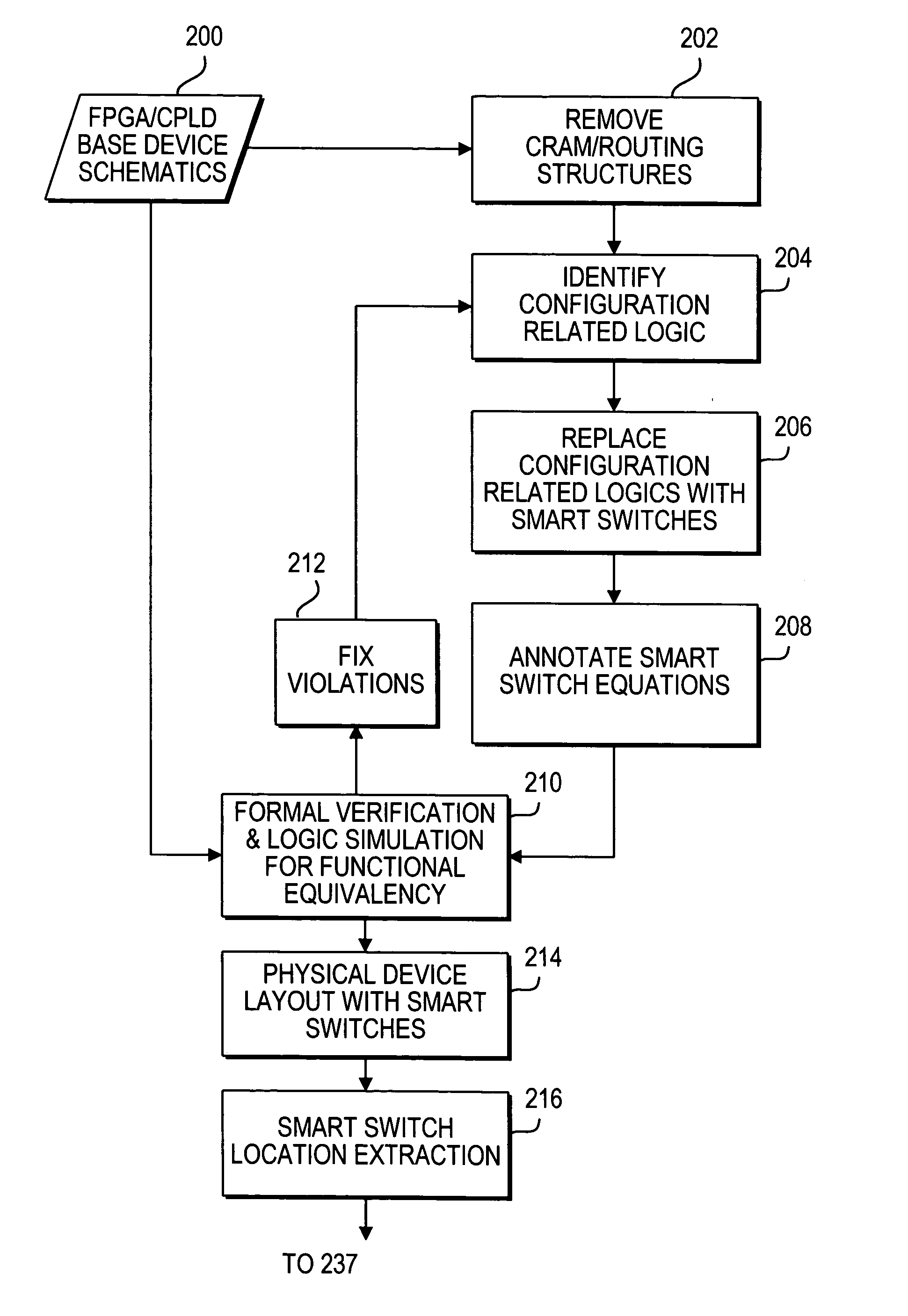
[0012] The present invention achieves greater optimization of the size, power savings, and performance of a mask-programmable logic device by modifying the base device architecture to facilitate the functionality of configuration-related logic circuitry of the source device without transistors. The modifications include replacing the source device's configuration-related logic and its CRAM configuration information with “smart” switches on the mask-programmable base device. A smart switch is a metal terminal, on top of which a metallization layer may be added to make a connection between one of the one or more input terminals of the switch and an output terminal of the switch. This connection is made based on Boolean equations that are derived from the functionality of the resource or resources the switch is replacing, and that are defined by the CRAM values associated with the resource or resources.

Problems solved by technology

While conventional programmable logic devices allow a user to easily design a device to perform a desired function, they invariably include resources that may not be used for a particular design.
Moreover, in order to accommodate general purpose routing and interconnect resources, and switching resources that allow signals from any logic resource to reach any desired routing and interconnect resource, conventional PLDs grow ever larger as more functionality is built into them, increasing the size and power consumption of such devices.
These configuration-related logics include a significant amount of transistor circuitry which increases the size and power consumption of such devices.

Method used


Image

  • Switch methodology for mask-programmable logic devices
  • Switch methodology for mask-programmable logic devices
  • Switch methodology for mask-programmable logic devices

Examples


Embodiment Construction

[0031] The present invention reduces the die area and power requirement of a mask-programmable logic device, while increasing its performance and yield, by providing smart switches in place of configuration-related logic circuitry and related CRAM configuration values on the base device. The smart switches may be used to facilitate, without transistors, the functionality of configuration-related logic circuitry of a circuit design previously implemented on another integrated circuit. The base device architecture, smart switch structure, interconnection, and conversion process are described below in more detail.

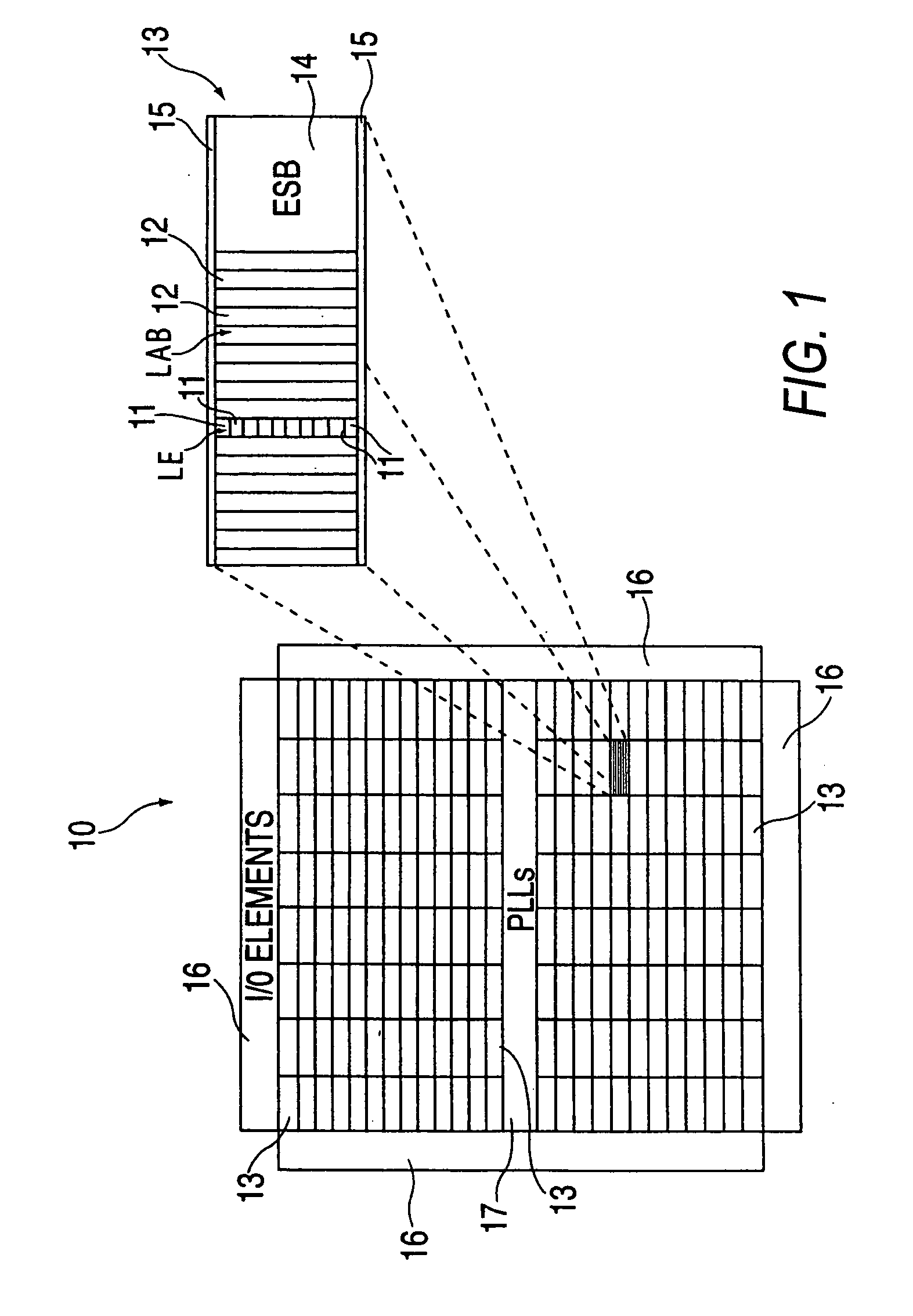
[0032] The invention will now be described with reference to FIGS. 1-15.

[0033] As seen in FIG. 1, one embodiment of a mask-programmable base device 10 constructed in accordance with the present invention includes an array of logic resources similar to those found in the APEX® and Stratix® families of programmable logic devices (i.e., possible source devices) sold by Altera C...


PUM


Abstract

A mask-programmable logic device that implements a pre-existing circuit design and that includes programmable smart switches is provided. The smart switches are metal terminals that may be programmed to perform configuration-related logic functions of the pre-existing circuit design.

Description

BACKGROUND OF THE INVENTION [0001] The present invention relates to mask-programmable logic devices, and more particularly, to methods of creating a mask-programmed logic device from a pre-existing circuit design. [0002] Programmable logic devices (PLDs) are well known. Early programmable logic devices were one-time configurable. For example, configuration may have been achieved by “blowing” (i.e., opening) fusible links. Alternatively, configuration may have been stored in a programmable read-only memory. These devices generally provided a user with the ability to configure the devices for “sum-of-products” (or “P-TERM”) logic operations. Later, such programmable logic devices incorporating erasable programmable read-only memory (EPROM) for configuration became available, allowing the devices to be reconfigured. [0003] Still later, programmable logic devices incorporating static random access memory (SRAM) elements for configuration became available. These devices, which also can b...

Claims


Application Information

Patent Timeline
IPC IPC(8): H03K19/177
CPCH03K19/17796
Inventor PARK, JONATHAN
Owner ALTERA CORP
Learn More