[0006] The present invention provides a method of forming an image on a label surface of an optical disk, the method comprising the steps of: forming a visible light characteristic changing layer in a position which can be viewed from a label surface side of an optical disk, the layer changing a characteristic of visible light having entered from the label surface side by
exposure to a laser beam used for recording a
signal and emitted from the part of the label surface; setting the optical disk on a turntable of an optical disk unit such that a label surface of the optical disk is oriented toward a direction in which a laser beam emitted from an
optical pickup is to enter; relatively moving the optical disk and the laser beam along a plane of the optical disk; and modulating the laser beam, in
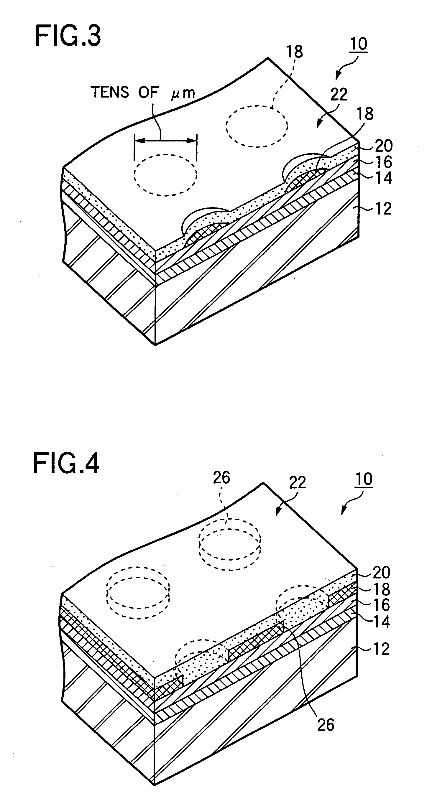
synchronism with the mutual movement, into a specific characteristic in accordance with image data to be printed, such as characters or graphic images, and emitting the modulated laser beam onto the visible light characteristic changing layer from the part of the label surface, wherein a reflection characteristic of the visible light having entered the visible light characteristic changing layer is changed by means of
exposure, thereby printing a corresponding image on the label surface. According to the label surface
image formation method, a laser beam output from the optical disk unit can be emitted onto the visible light characteristic changing layer formed in an area which can be viewed from the part of a label surface of an optical disk, thereby changing the
reflectivity, permeability, or light-scattering characteristic of the visible light. In this way, corresponding images, such as characters or graphic images, can be formed on the label surface, thereby obviating a necessity of writing images with a pen or printing images with a printer.
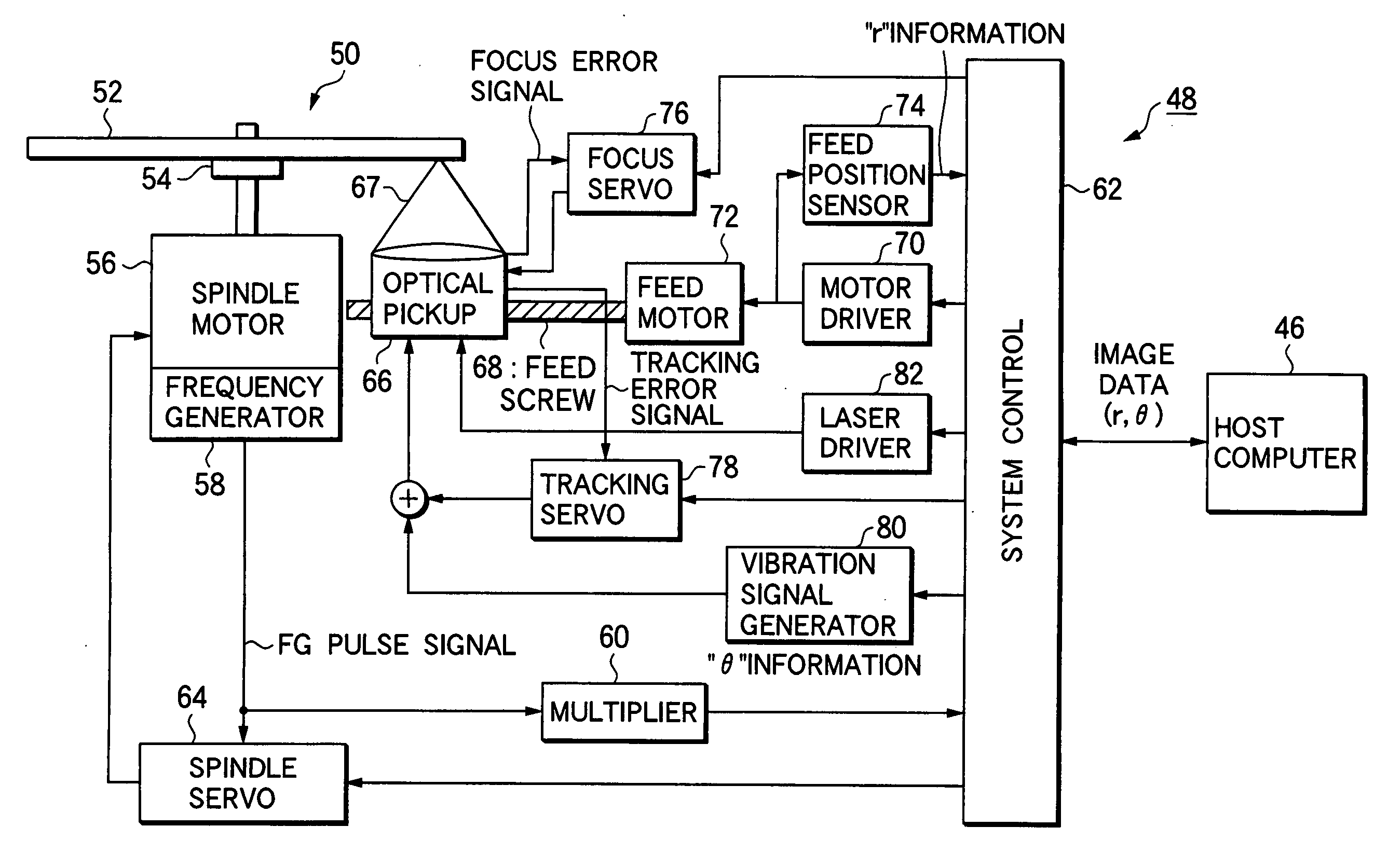
[0008] The present invention also provides an optical disk unit comprising: a relative movement mechanism for relatively moving an optical disk set on a turntable while a label surface is oriented in a direction in which a laser beam is to enter, and a laser beam emitted from an optical
pickup along a plane of the optical disk; a
laser modulation circuit for modulating a laser beam emitted from the optical
pickup; and a circuit for controlling the relative movement mechanism and the
laser modulation circuit, wherein the
control circuit performs control operation so as to form an image on a visible light characteristic changing layer by controlling the relative movement mechanism to relatively move the optical disk and the laser beam and controlling the
laser modulation circuit in accordance with image data, such as characters or graphic images, to be formed on a label surface of the optical disk, thereby modulating a laser beam output from the optical
pickup on the basis of the image data, and thereby forming an image corresponding to the image data on the visible light characteristic changing layer, a characteristic of
reflectivity, permeability or
light scattering of the visible light is changed by the
exposure of the laser beam, which can be viewed from the part of a label surface of the optical disk. The optical disk unit enables implementation of the label surface
image formation method according to the present invention.
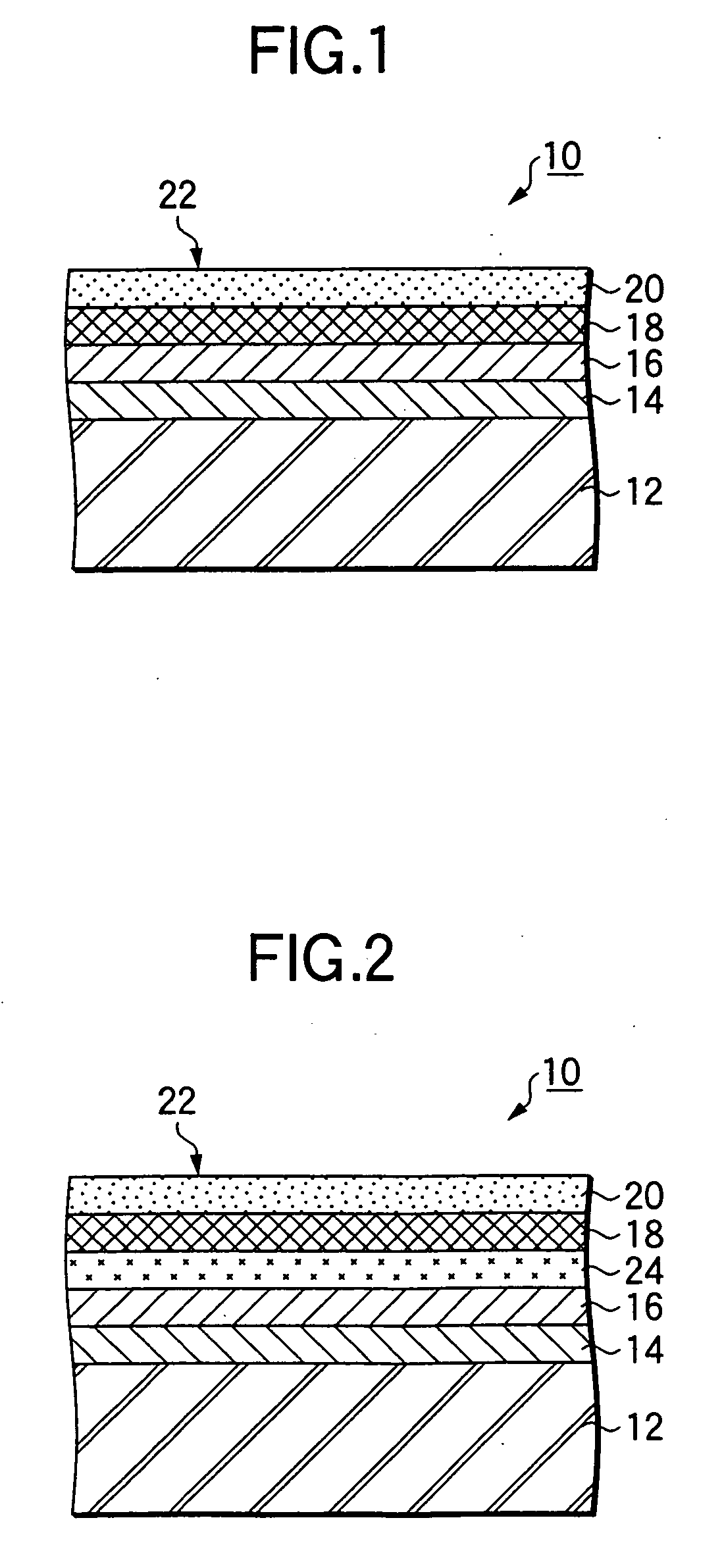
[0010] The present invention also provides an optical disk comprising a visible light characteristic changing layer which changes a visible characteristic of a visible light by exposure to a laser beam having entered from a label surfaces and which is formed in a location capable of being viewed from the part of the label surface. The optical disk enables implementation of the label surface
image formation method according to the present invention. Since the visible light characteristic changing layer is formed integrally on an optical disk, occurrence of vibration caused by
mass eccentricity during high-speed rotation, and occurrence of failure caused by exfoliation of a label within a drive can be prevented, as compared with a label pasting method.

