Method and apparatus to compensate for receiver frequency error in noise estimation processing

US20050281324A1Active Publication Date: 2005-12-22TELEFON AB LM ERICSSON (PUBL)

Image

  • Method and apparatus to compensate for receiver frequency error in noise estimation processing
  • Method and apparatus to compensate for receiver frequency error in noise estimation processing
  • Method and apparatus to compensate for receiver frequency error in noise estimation processing

Examples


Embodiment Construction

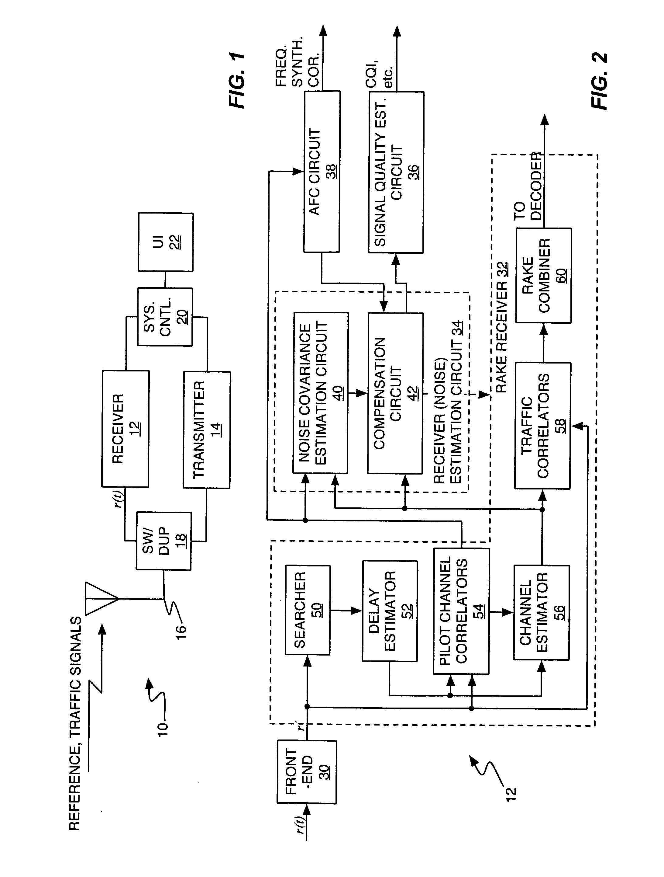
[0020]FIG. 1 illustrates a wireless communication device 10 that is configured in accordance with one or more embodiments of the present invention. Device 10 may comprise essentially any type of wireless communication device or system, and thus may comprise a mobile station, a Portable Digital Assistant (PDA), a pager, a laptop / palmtop computer, etc. In at least one embodiment, the wireless communication device 10 comprises a mobile station configured for operation in a cellular communication network. In at least one embodiment, the wireless communication device 10 comprises a mobile station configured for operation in a Wideband CDMA (W-CDMA) communication network.

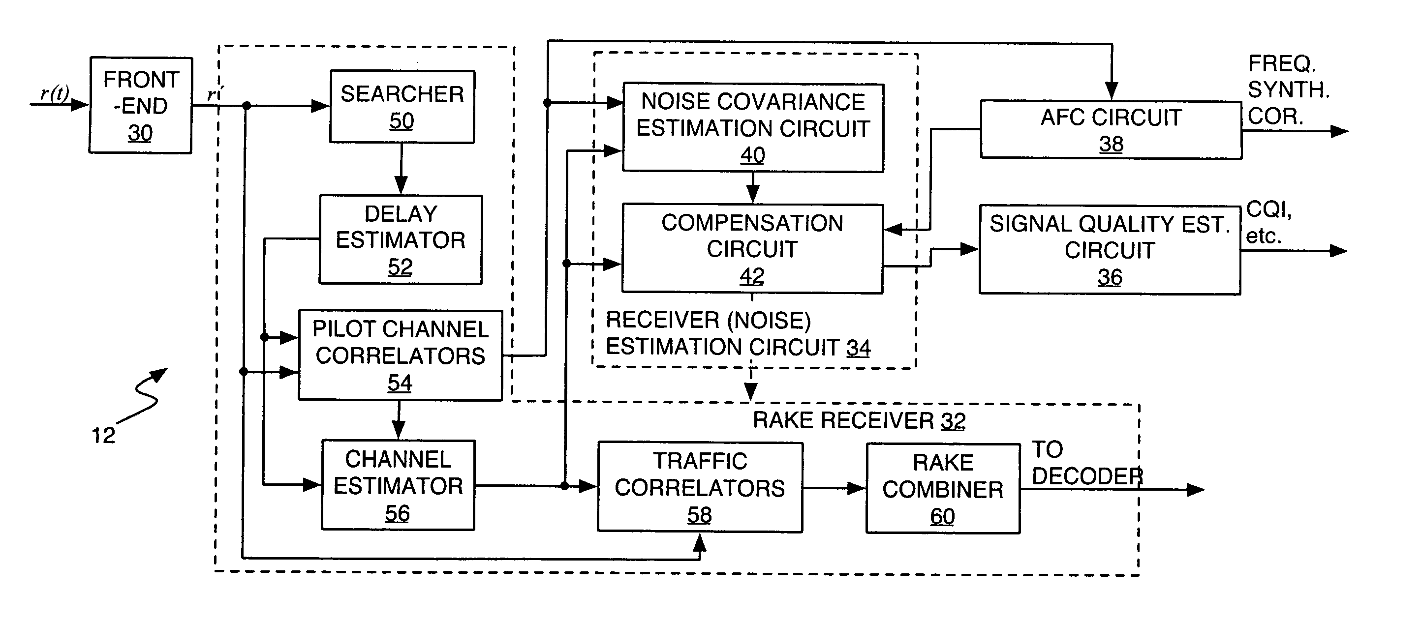
[0021] Thus, with the understanding that device 10 is not limited by the disclosed illustrations, FIG. 1 depicts an arrangement wherein device 10 is adapted for wireless communication and comprises a receiver 12 to receive and process received signals, a transmitter 14 to generate and transmit signals, one or more antenn...


PUM


Abstract

A receiver circuit provides improved noise estimation processing by at least partially removing receiver frequency error bias. An initial noise estimate is compensated using an error term based on the observed receiver frequency error, and the resulting compensated noise estimate can be used to improve other signal processing in the receiver. For example, the receiver may use compensated noise estimates to generate signal quality estimates, e.g., Signal-to-Interference (SIR) estimates, having improved accuracy. Additionally, or alternatively, the receiver may use the compensated noise estimates to generate RAKE combining weights having improved noise suppression characteristics. In an exemplary embodiment, the initial noise estimate is a noise correlation matrix generated from a received reference signal, e.g., pilot symbols, and the error term is an error matrix directly generated using he observed receiver frequency error and channel estimates taken from the reference signal.

Description

RELATED APPLICATIONS [0001] This application claims priority under 35 U.S.C. § 119(e) from the following U.S. provisional application: Application Ser. No. 60 / 580,202, as filed on Jun. 16, 2004. That application is expressly incorporated by reference herein.BACKGROUND OF THE INVENTION [0002] The present invention generally relates to wireless communication networks, and particularly relates to noise estimation processing in wireless communication receivers. [0003] Noise estimation represents an integral part of receiver processing in wireless communication networks. For example, many types of modern wireless communication networks use “best-effort” packet data channels, where individual users are served at the highest data rates that can be supported given the prevailing radio and network conditions. Accurate noise estimation at the receivers is essential to the signal quality calculations performed at those receivers and, in turn, those signal quality calculations set the network's...

Claims


Application Information

Patent Timeline
22 Dec 2005
Publication
US20050281324A1
IPC
H04L1/20; H04L27/00
CPC
H04B2201/709727; H04B1/10; H04L2027/0065; H04L1/20
Inventors
WALLEN, ANDERS