
Burst mode optical receiver and system and method therefor

a technology of optical receiver and burst mode, applied in the field of communication system, can solve the problems of reducing transmission speed, affecting system sensitivity and bandwidth, and increasing system complexity

Active Publication Date: 2005-12-22
IND TECH RES INST
View PDF14 Cites 15 Cited by
  • Summary
  • Abstract
  • Description
  • Claims
  • Application Information

AI Technical Summary

Benefits of technology

[0007] Accordingly, an embodiment of the present invention is directed to a burst mode optical receiver and system and method that obviate one or more of the problems due to limitations and disadvantages of the related art.

Problems solved by technology

Data encoding and decoding required in burst mode transmission, however, undesirably increases system complexity and reduces transmission speed.
As the logic transitions become difficult to identify, the effects of noise and pulse width distortion adversely affect the system sensitivity and bandwidth.

Method used


Image

  • Burst mode optical receiver and system and method therefor
  • Burst mode optical receiver and system and method therefor
  • Burst mode optical receiver and system and method therefor

Examples


Embodiment Construction

[0017] Reference will now be made in detail to present embodiments of the present invention, examples of which are illustrated in the accompanying drawings. Wherever possible, the same reference numbers will be used throughout the drawings to refer to the same or like parts.

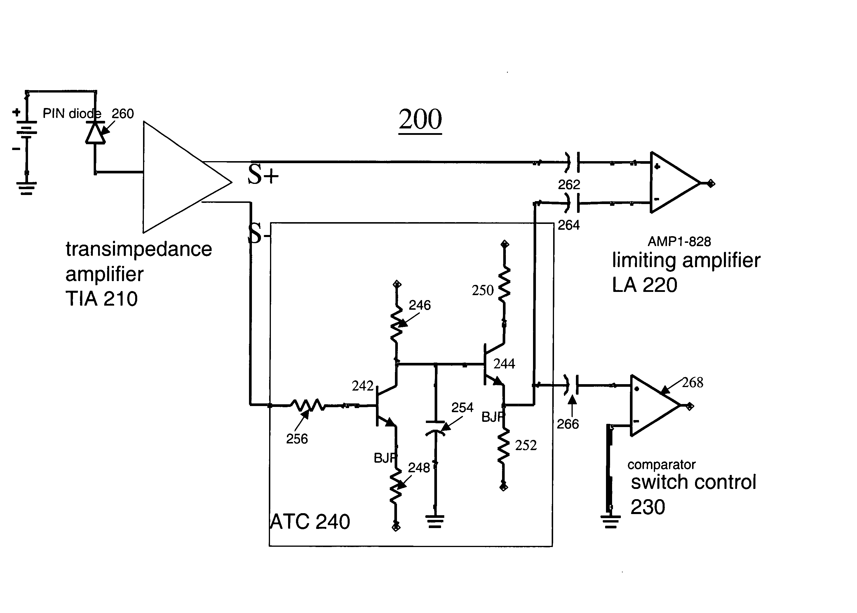
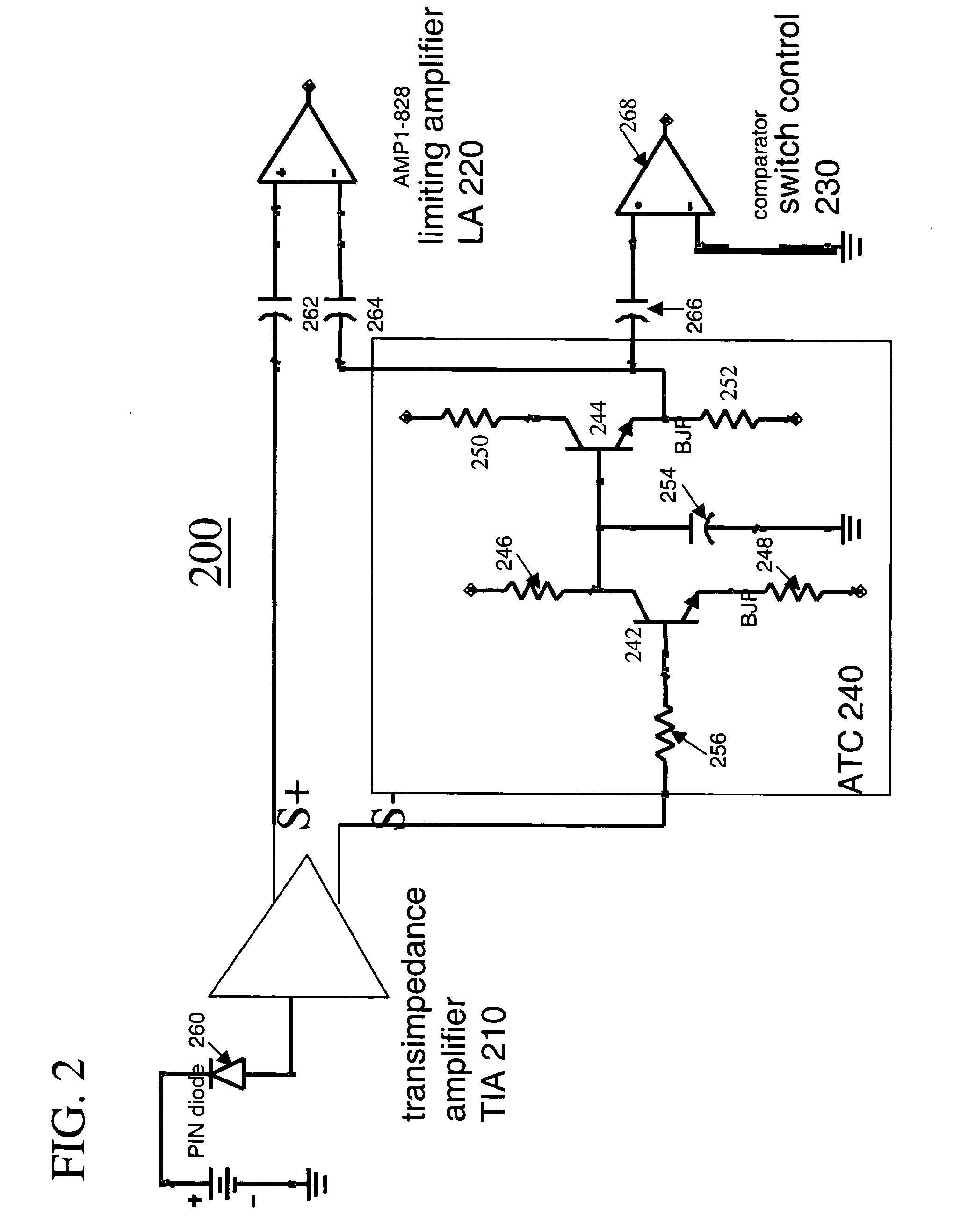
[0018]FIG. 2 is a schematic view of an example of a burst mode optical receiver in a system according to an embodiment of the present invention. FIG. 3 is a schematic view that illustrates an example of a transmission system having, e.g., a passive optical network (“PON”), to which embodiments consistent with the present invention may be applied. Burst mode optical receiver 200 (shown in FIG. 3 in conjunction with office line terminal or “OLT 300”) comprises a transimpedance amplifier (“TIA 210”), a limiting amplifier (“LA 220”), a switch control 230, and an automatic threshold control (“ATC 240”). ATC 240 further comprises transistors 242 and 244 configured as a common emitter circuit coupled with an emitter fo...


PUM


Abstract

A communications system includes an optical receiver for receiving optical signals and for converting the optical signals into electrical signals, a transimpedance amplifier (“TIA”) for filtering the electrical signals, a limiting amplifier coupled with the TIA, an automatic threshold control (“ATC”) coupled with the TIA for providing a reference voltage for the limiting amplifier. The ATC further includes a common emitter circuit and an emitter follower circuit, wherein logic high signals and logical low signals in the electrical signals are determined based on the reference voltage output from the ATC.

Description

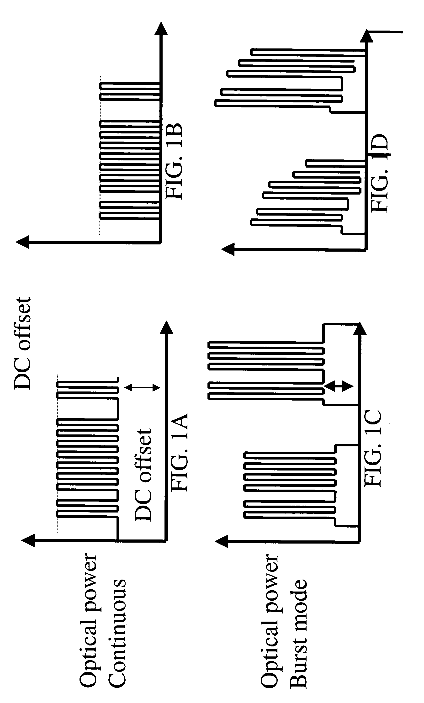
BACKGROUND OF THE INVENTION [0001] 1. Field of the Invention [0002] The present invention generally relates to a communications system and, more particularly, to a burst mode optical receiver and system and method therefor. [0003] 2. Description of the Related Art [0004] Optical communications systems utilize receivers capable of receiving data continuously transmitted (i.e., in continuous mode) or data transmitted in a burst mode (i.e., a direct unencoded transmission of data wherein the data being transmitted have long strings of only 1s or long strings of only 0s). FIGS. 1A, 1B, 1C and 1D are diagrams illustrating waveforms of data transmission in continuous mode and in burst mode, each with and without direct current (“DC”) offset. In particular, FIGS. 1A and 1B diagrams that illustrate waveforms of data transmission in a continuous mode with and with DC offset, respectively. FIGS. 1C and 1D are diagrams that illustrate waveforms of data transmission in a burst mode with and wit...

Claims


Application Information

Patent Timeline
Patent Type & Authority Applications(United States)
IPC IPC(8): H04B10/06H04B10/158
CPCH04B10/695
Inventor DUANMU, JIA-JAYCHOU, YUN-LUNGLEE, SHI-WEI
Owner IND TECH RES INST
Learn More