Image processing method and system for microfluidic devices

a microfluidic device and image processing technology, applied in the field of image processing technology, can solve the problems of difficult and sometimes impossible formation of high-quality crystals, inability to form highly ordered crystal structures, and requiring much trial and error and patience on the part of researchers, so as to simplify the image processing system, improve the sensitivity of the image processing method and system, and improve the speed of imaging analysis

Inactive Publication Date: 2005-12-22
FLUIDIGM CORP
View PDF77 Cites 51 Cited by
  • Summary
  • Abstract
  • Description
  • Claims
  • Application Information

AI Technical Summary

Benefits of technology

[0015] Numerous benefits are achieved using the invention over conventional techniques. Depending upon the embodiment, one or more of these benefits may be achieved. For example, certain embodiments of the present invention improves the speed of imaging a

Problems solved by technology

In practice however, forming a high quality crystal is generally difficult and sometimes impossible, requiring much trial and error and patience on the part of the rese

Method used


Image

  • Image processing method and system for microfluidic devices
  • Image processing method and system for microfluidic devices
  • Image processing method and system for microfluidic devices

Examples


Embodiment Construction

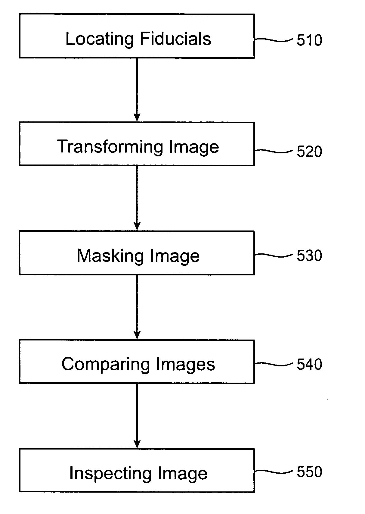
[0044] The present invention is directed to image processing technology. More particularly, the invention provides an image processing method and system for detecting changes of an imaged object. Merely by way of example, the invention has been applied to crystallization in a microfluidic device. But it would be recognized that the invention has a much broader range of applicability.

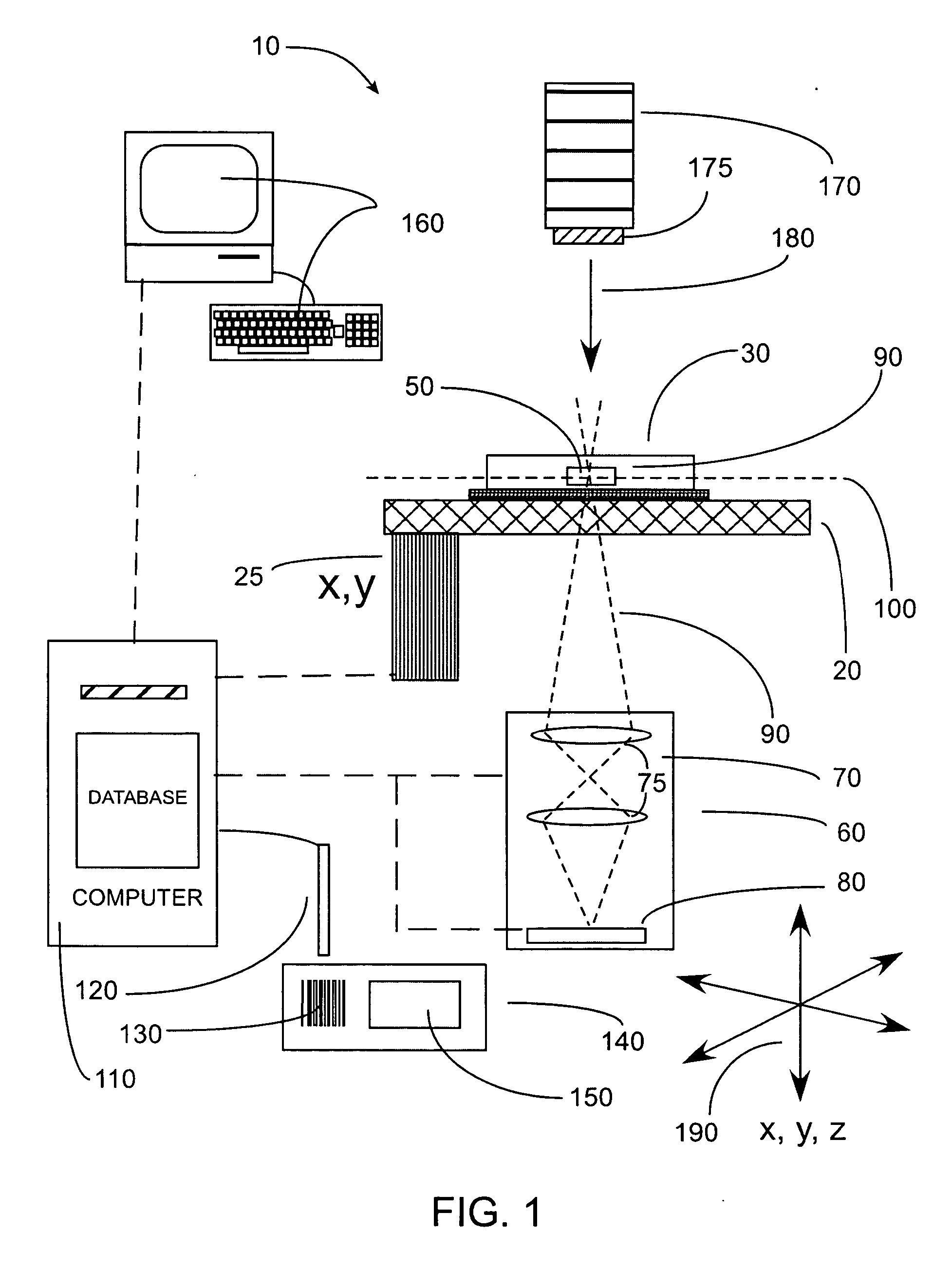
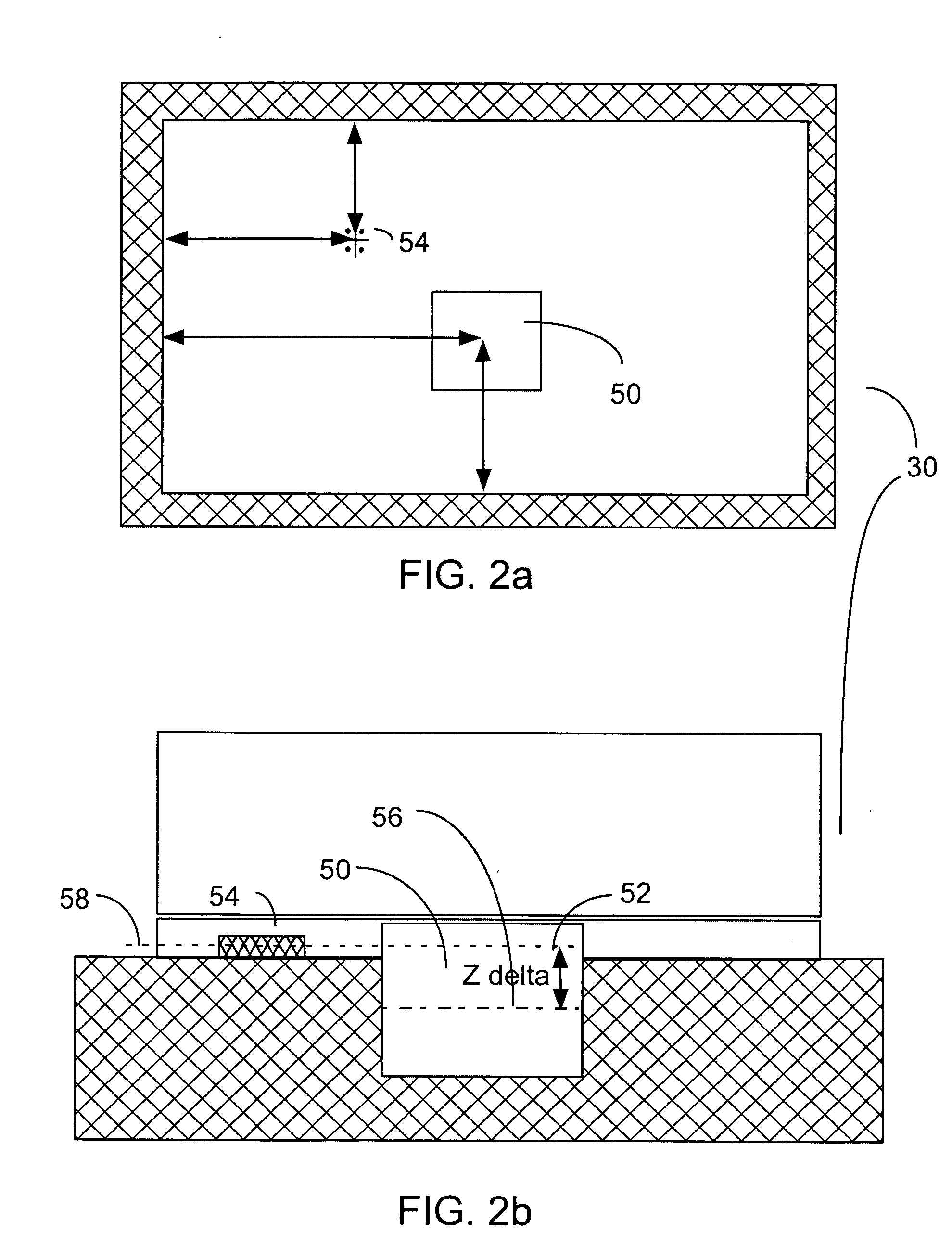
[0045]FIG. 1 is a simplified diagram for an imaging system according to an embodiment of the present invention. FIGS. 2a and 2b are simplified diagrams for a top view and cross-sectional view of a microfluidic device according to an embodiment of the present invention. The microfluidic device as shown in FIGS. 2a and 2b can be used in conjunction with the imaging system as shown in FIG. 1. These diagrams are merely examples, which should not unduly limit the scope of the claims herein. One of ordinary skill in the art would recognize many variations, alternatives, and modifications.

[0046] Imaging syste...


PUM

PropertyMeasurementUnit
Distanceaaaaaaaaaa
Crystallization enthalpyaaaaaaaaaa

Abstract

A method for processing an image of a microfluidic device. The method includes receiving a first image of a microfluidic device. The first image corresponds to a first state. Additionally, the method includes receiving a second image of the microfluidic device. The second image corresponds to a second state. Moreover, the method includes transforming the first image and the second image into a third coordinate space. Also, the method includes obtaining a third image based on at least information associated with the transformed first image and the transformed second image, and processing the third image to obtain information associated with the first state and the second state.

Description

CROSS-REFERENCES TO RELATED APPLICATIONS [0001] This application claims priority to U.S. Provisional Application No. 60 / 490,712, filed Jul. 28, 2003, which is incorporated by reference herein. [0002] Additionally, U.S. application Ser. No. 10 / 851,777 filed May 20, 2004 and titled “Method and System for Microfluidic Device and Imaging Thereof” is incorporated by reference herein.STATEMENT AS TO RIGHTS TO INVENTIONS MADE UNDER FEDERALLY SPONSORED RESEARCH OR DEVELOPMENT [0003] NOT APPLICABLE REFERENCE TO A “SEQUENCE LISTING,” A TABLE, OR A COMPUTER PROGRAM LISTING APPENDIX SUBMITTED ON A COMPACT DISK [0004] NOT APPLICABLE COPYRIGHT NOTICE [0005] A portion of this application contains computer codes, which are owned by Fluidigm Corporation. All rights have been preserved under the copyright protection, Fluidigm Corporation ©2004. BACKGROUND OF THE INVENTION [0006] The present invention is directed to image processing technology. More particularly, the invention provides an image proces...

Claims


Application Information

Patent Timeline
IPC IPC(8): B01L3/00B29CC12Q1/68G06T7/00G06V20/69
CPCB01L3/5027G06K9/00127G06K9/00134G06K9/6232G06T2207/30004G06T7/0012G06T7/0028G06T7/2053G06T7/0008G06T7/33G06T7/254G06V20/69G06V20/693G06V10/7715G06F18/213G06F18/00
Inventor TAYLOR, COLIN JONSUN, GANGDUBE, SIMANT
Owner FLUIDIGM CORP
Why Eureka
Try Eureka