Speed control method for working vehicle

Active Publication Date: 2005-12-22
KANZAKI KOKYUKOKI MFG
View PDF6 Cites 25 Cited by
  • Summary
  • Abstract
  • Description
  • Claims
  • Application Information

AI Technical Summary

Benefits of technology

[0011] An object of the present invention is to provide a speed control method for a working vehicle by which a pattern of increase of vehicle traveling speed in response to acceleration operation of a speed change ope

Problems solved by technology

However, if this governing is performed, the variation range of engine rotation speed becomes too wide.
However, even when the accelerator operation member is operated rapidly, the vehicle traveling speed cannot change desirably swiftly because the slow response of the speed ratio change.
Further, the reduction of variation range of the engine rotation speed is disadvantageous in ensuring sufficient engine torque against high load applied on the engine.
Further, if the governing is based

Method used


Image

  • Speed control method for working vehicle
  • Speed control method for working vehicle
  • Speed control method for working vehicle

Examples


Example

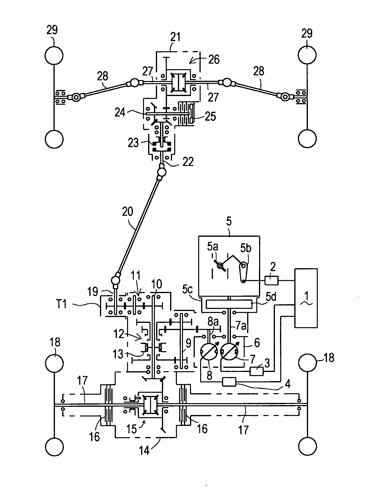
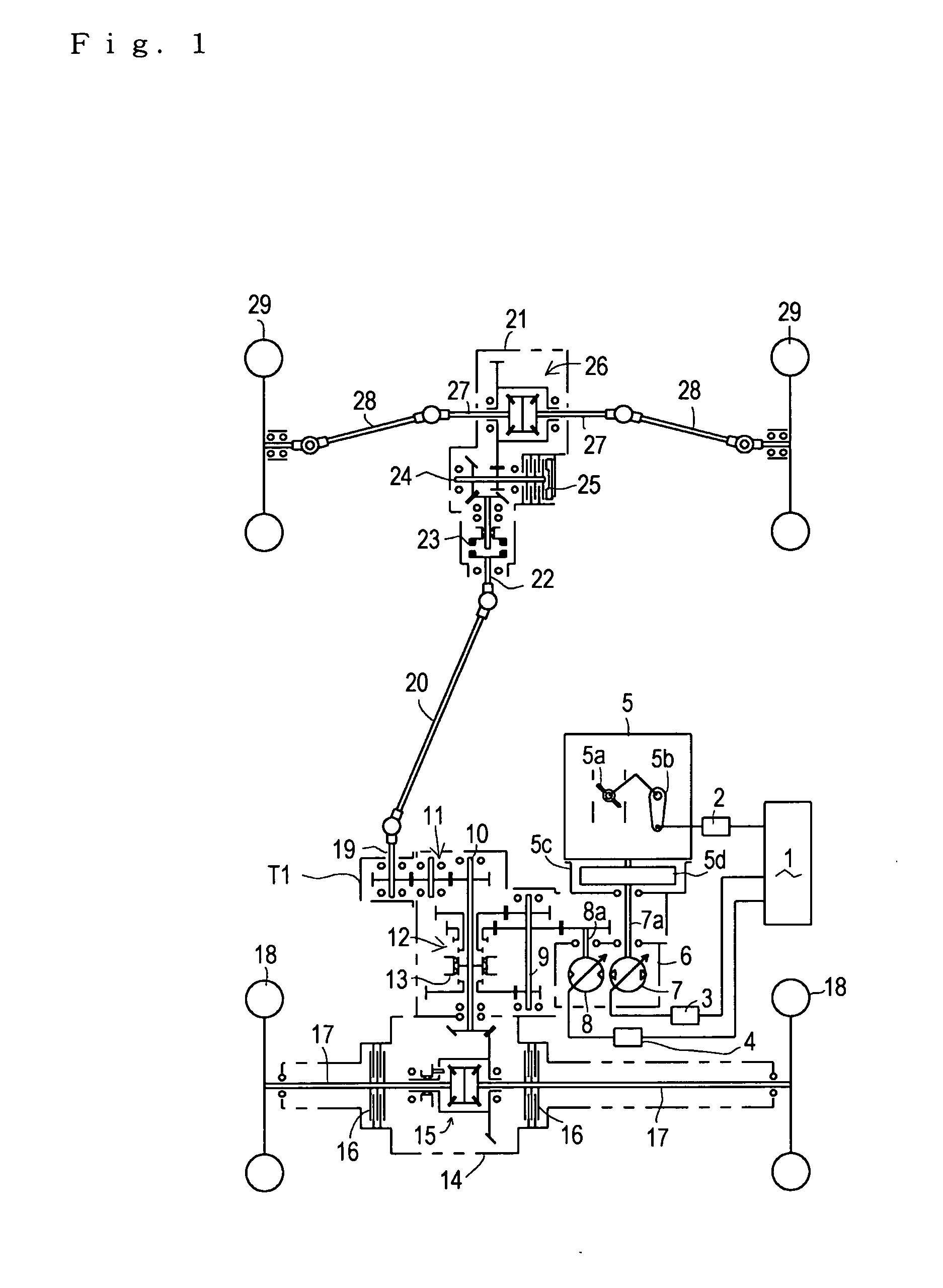
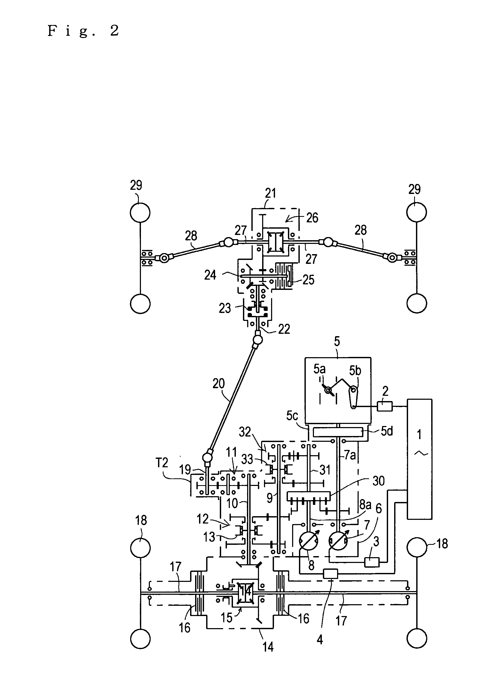
[0053] FIGS. 1 to 3 illustrate respective exemplary working vehicles employing the present invention. A working vehicle shown in FIG. 1 has an HST, serving as a stepless speed change mechanism, combined with a gear-type auxiliary speed change mechanism. Each of working vehicles shown in FIGS. 2 and 3 has an HMT, which is constructed by combining a HST with a planetary gear mechanism, serving as a stepless speed change mechanism, combined with a gear-type auxiliary speed change mechanism. The HMT in FIG. 2 combines torques of a pump shaft and a motor shaft of the HST with each other by planet gears. The HMT in FIG. 3 combines torques of an engine output shaft and an auxiliary speed change drive shaft for driving the auxiliary speed change mechanism with each other by planet gears.

[0054] Firstly, explanation will be given on a drive system of each of the vehicles in FIGS. 1 to 3. As a common construction among the vehicles, a flywheel 5d is fixed on an end of an output shaft of an en...


PUM


Abstract

An object of the present invention is to provide a working vehicle having such a fine traveling feel that the vehicle traveling speed is increased in proportion to operation of a speed change operation means similar to a normal passenger car, while reducing noise and fuel consumption of an engine at the time of traveling in middle or high speed. While an operation degree of the speed change operation member is increased from 0 to a certain value, the increase of the vehicle traveling speed is produced by a first increase rate of the engine rotation speed and a first increase rate of a speed ratio (output/input rotation speed ratio of a speed change mechanism) increase rate, and while the operation degree of the speed change operation member is increased from the certain value, the engine rotation speed is kept to be the rated value and corresponding thereto, the increase rate of the speed ratio is set to a second increase rate of the speed ratio larger than the first increase rate of the speed ratio so that the vehicle traveling speed is always increased substantially in proportion to the acceleration operation of the speed change operation member.

Description

BACKGROUND OF THE INVENTION [0001] 1. Field of the Invention [0002] The present invention relates to a method for controlling speed by controlling an output / input rotation speed ratio (hereinafter, simply referred to as a “speed ratio”) of a speed change mechanism using a hydrostatic stepless transmission (HST) (including a hydraulic mechanical transmission (HMT)) and an engine rotation speed by an electronic governor, the method being adapted to a working vehicle, such as an agricultural tractor. [0003] 2. Related Art [0004] Conventionally, there is a well-known working vehicle, such as an agricultural tractor, comprising an HMT or another speed change mechanism using an HST; an electronic governor for controlling vehicle traveling speed; and an accelerator operation member for setting the vehicle traveling speed, such as a pedal or a lever, manipulated by an operator. The electric governor controls a speed ratio of the speed change mechanism and an engine rotation speed in corresp...

Claims


Application Information

Patent Timeline
IPC IPC(8): B60W10/04B60W10/06B60W10/10B60W10/101B60W10/103B60W30/14F02D29/02F16H47/02F16H47/04F16H59/06F16H59/38F16H61/40F16H61/425F16H61/435F16H61/66
CPCB60W10/06B60W10/103B60W30/188B60W2520/10B60W2530/10B60W2540/10B60W2540/106B60W2720/10F16H47/02F16H47/04F16H61/462F16H2059/6853
Inventor ISHII, NORIHIROSHIMIZU, HIROAKI
Owner KANZAKI KOKYUKOKI MFG
Why Eureka
Try Eureka