Identification of a modular machine component

a modular machine and component technology, applied in the field of plastic processing machines, can solve the problems of affecting the operation of the machine, the change of the existing screw-cylinder configuration, and the continuous adjustment of the control software, so as to minimize the complexity of wiring and good connection

Active Publication Date: 2005-12-22
SUMITOMO SHI DEMAG PLASTICS MACHINERY
View PDF5 Cites 11 Cited by
  • Summary
  • Abstract
  • Description
  • Claims
  • Application Information

AI Technical Summary

Benefits of technology

[0019] According to another feature of the present invention, the memory device may be constructed as programmable non-volatile memory, in particular as EEPROM (Electrically Erasable and Programmable Read-Only Memory) to allow changes in the configuration also later, for example to provide an additional external heating zone, and to store these changes of the component-specific parameters in the memory device, without requiring an exchange of the memory device.
[0020] According to another feature of the present invention, the memory device may be part of a decentralized

Problems solved by technology

This means for example in relation to the plasticizing unit which is used in many different screw-cylinder configurations a very complicated programming process for each delivered machine.
This is also a major drawback in connection with possible changes of an existing screw-cylinder configuration, as can be encountered in the exceptional case during material change but in particular upon replacement of defective or worn screws by new ones.
The continuous adjustment of the control software is also a source of errors as is any change of existing software.
Compounding this problem is the fact that this spec

Method used


Image

  • Identification of a modular machine component
  • Identification of a modular machine component
  • Identification of a modular machine component

Examples


Embodiment Construction

[0026] Throughout all the Figures, same or corresponding elements are generally indicated by same reference numerals. These depicted embodiments are to be understood as illustrative of the invention and not as limiting in any way. It should also be understood that the drawings are not necessarily to scale and that the embodiments are sometimes illustrated by graphic symbols, phantom lines, diagrammatic representations and fragmentary views. In certain instances, details which are not necessary for an understanding of the present invention or which render other details difficult to perceive may have been omitted.

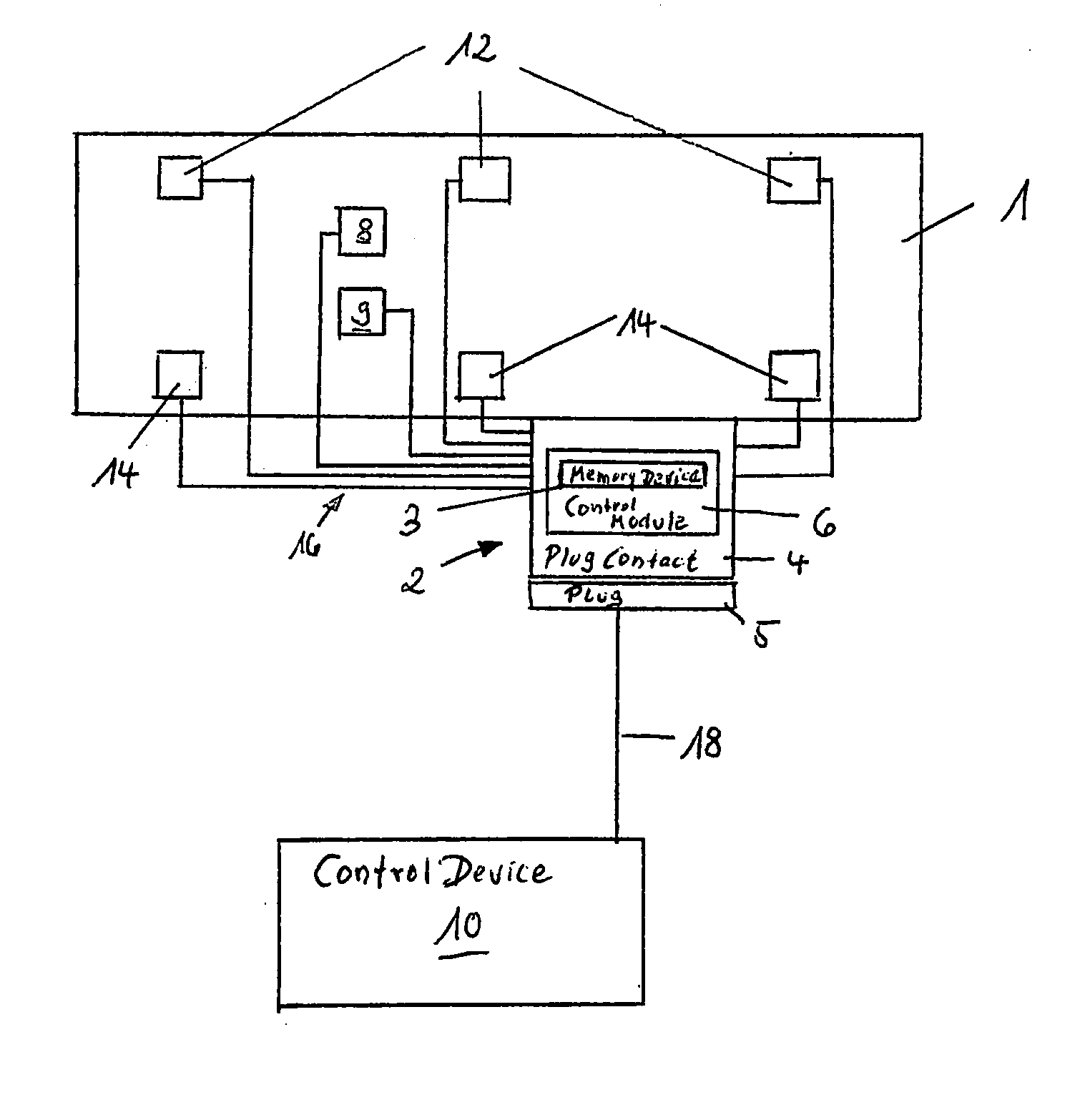
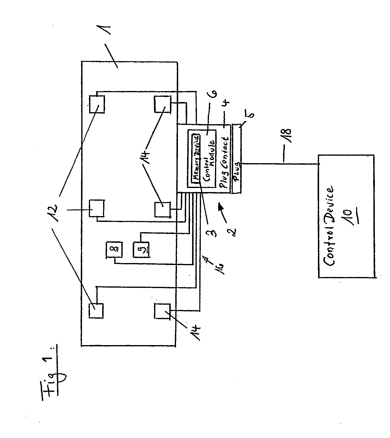
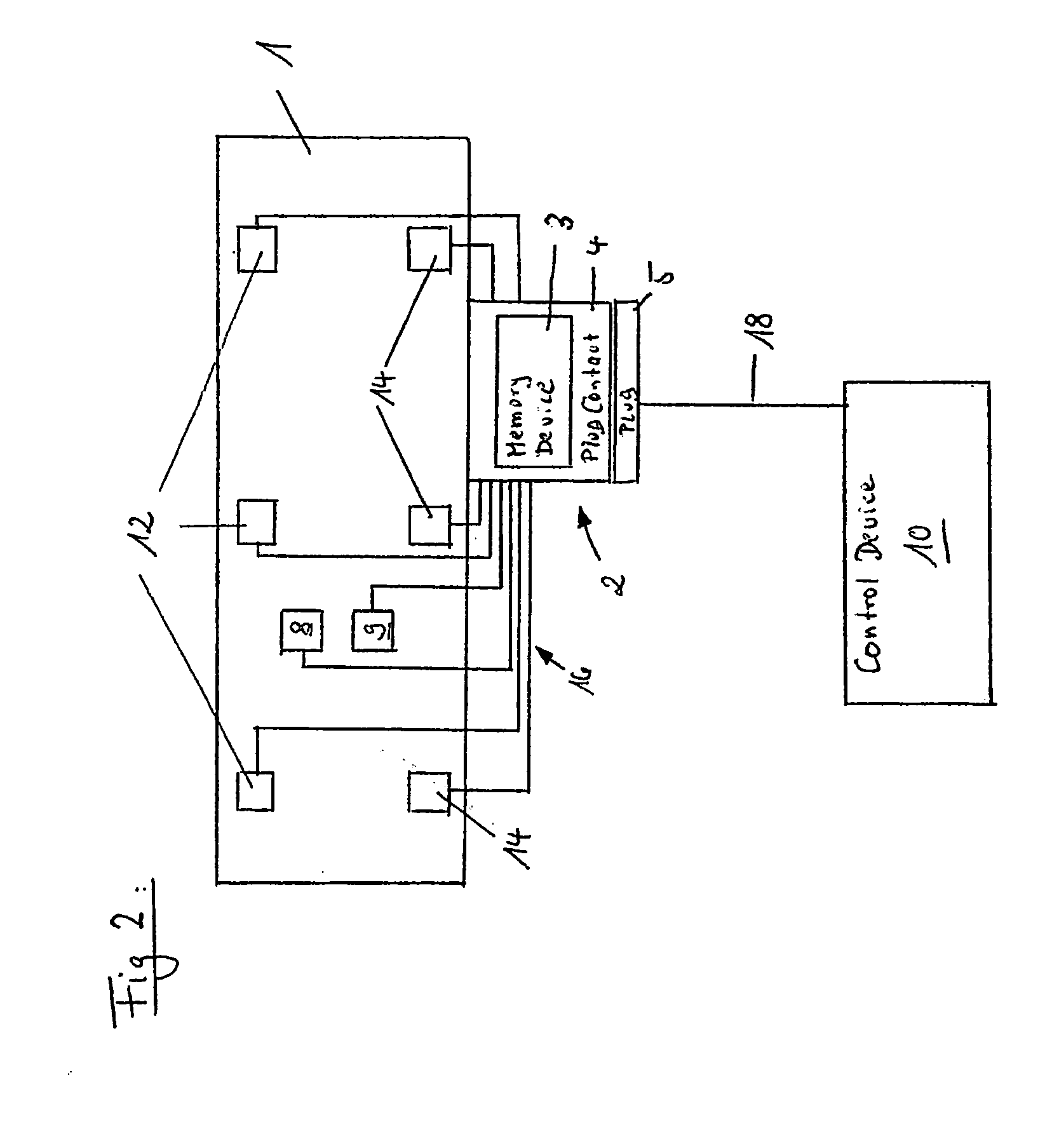
[0027] An unillustrated injection molding machine includes a control device 10 configured as stored-program controller (SPC) and a plasticizing unit 1 shown only schematically and having a plasticizing screw and a plasticizing cylinder on which a plug connection 2 with a plug contact 4 and a plug 5 is provided. The plasticizing unit 1 includes various sensors 8 and actuators...


PUM

PropertyMeasurementUnit
Temperatureaaaaaaaaaa
Thermoelectricityaaaaaaaaaa

Abstract

A plastics processing machine, in particular injection molding machine or extruder, includes at least one component represented by a clamping unit, feed and metering apparatus, plasticizing unit, injection unit, or separate injection apparatus, and characterized by specific parameters for carrying out at least one working or process step. A control device is connected to the at least one component and configured to control the at least one component, with the component-specific parameters being useable in the control device for control of the component. Provided for the component is a separate memory device in which the component-specific parameters are stored and can be transmitted to the control device prior to or upon startup of operation of the component.

Description

CROSS-REFERENCES TO RELATED APPLICATIONS [0001] This application is a continuation of prior filed copending PCT International application no. PCT / EP2004 / 001130, filed Feb. 7, 2004, which designated the United States and on which priority is claimed under 35 U.S.C. §120 and which claims the priority of German Patent Application, Serial No. 103 08 386.3, filed Feb. 27, 2003, pursuant to 35 U.S.C. 119(a)-(d), the subject matter of which is / are incorporated herein by reference.BACKGROUND OF THE INVENTION [0002] The present invention relates to a plastics processing machine, in particular to an injection molding machine or an extruder, and more particularly to a plastics processing machine having at least one component being controlled by a control device. [0003] Nothing in the following discussion of the state of the art is to be construed as an admission of prior art. [0004] German Offenlegungsschrift DE 199 58 790 C2 discloses a machine for making parts of plastic or rubber, whereby a...

Claims


Application Information

Patent Timeline
IPC IPC(8): B29C45/17B29C45/76B29C48/03B29C48/395B29C48/875B29C48/92G05B19/042G05B19/05
CPCB29C45/176G05B2219/2624B29C47/0009B29C47/82B29C47/92B29C2045/1796B29C2945/7604B29C2947/92038B29C2947/92209B29C2947/92295B29C2947/92361B29C2947/92438B29C2947/92533B29C2947/92619B29C2947/92704B29C2947/9279B29C2947/92933G05B19/0426G05B19/056G05B2219/15004G05B2219/25092G05B2219/25099G05B2219/25103G05B2219/25109B29C45/766B29C48/875B29C48/83B29C48/92B29C2948/92209B29C2948/92704B29C48/03B29C2948/92038B29C2948/92295B29C2948/92361B29C2948/92438B29C2948/92533B29C2948/92619B29C2948/9279B29C2948/92933Y02P90/02B29B7/728
Inventor DACHS, OSWALDLUTTICH, KARL RUDOLFWARNECKE, GERD
Owner SUMITOMO SHI DEMAG PLASTICS MACHINERY
Why Eureka
Try Eureka