Zero-clearance ultra-high-pressure gas compressor

a gas compressor, ultra-high-pressure technology, applied in the direction of piston pumps, lighting and heating apparatus, container discharging methods, etc., can solve the problems of pressure energy loss in the gas, less efficiency of conventional reciprocating positive displacement compressors,

Active Publication Date: 2005-12-29
AIR PROD & CHEM INC
View PDF20 Cites 36 Cited by
  • Summary
  • Abstract
  • Description
  • Claims
  • Application Information

AI Technical Summary

Benefits of technology

[0017] This embodiment also may further comprise any of (1) cooling means within the compression cylinder adapted to effect heat transfer therein between the compression liquid and a gas; (2) a cooler adapted to cool the compression liquid as it flows between the compression cylinder and the pump; (3) a drain eductor having a high pressure inlet, a low pressure inlet, and an outlet, wherein the high pressure inlet is in flow communication with the discharge of the pump, the low pressure inlet is in flow communication w

Problems solved by technology

Conventional reciprocating positive-displacement compressors may become less efficient as the discharge pressure increases because of the clearance or dead volume required between the moving compressor element (e.g., piston or diaphragm) and the compressor casing.
Because of this clearance volume, a small but significant amount of gas remains in the compressor at the

Method used


Image

  • Zero-clearance ultra-high-pressure gas compressor
  • Zero-clearance ultra-high-pressure gas compressor
  • Zero-clearance ultra-high-pressure gas compressor

Examples


example

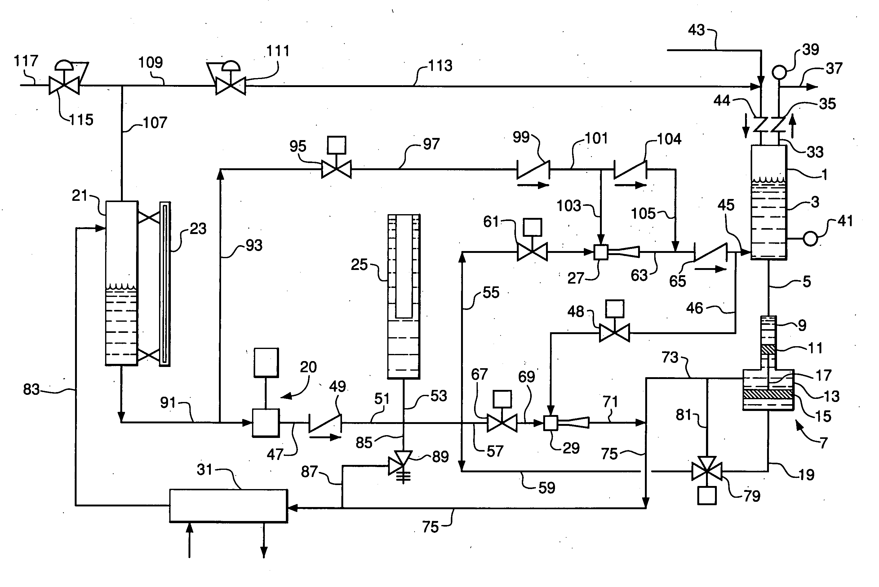
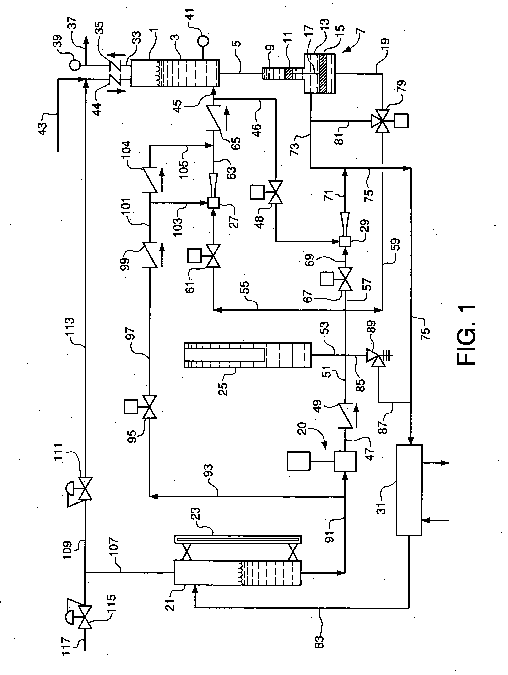
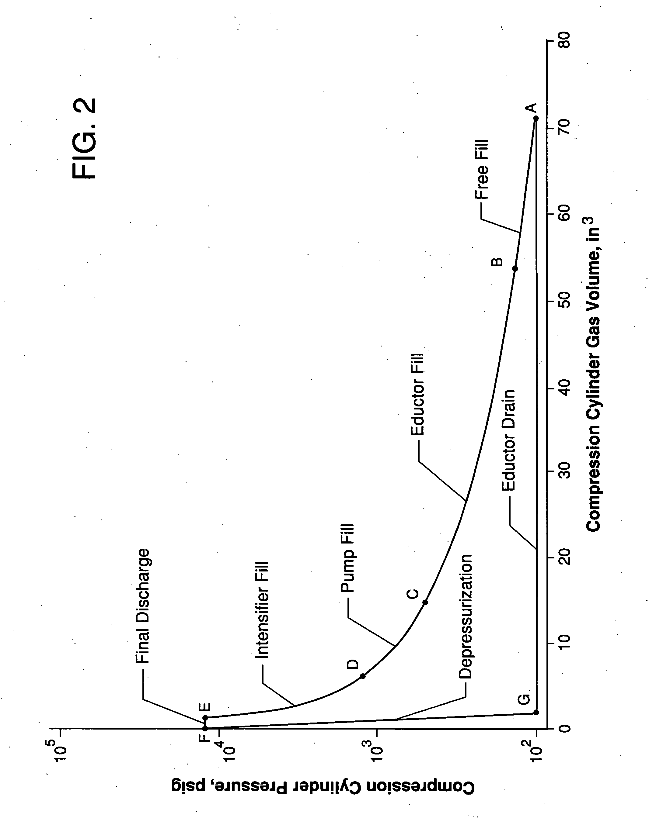
[0109] The following Example illustrates an embodiment of the present invention but does not limit the invention to any of the specific details described therein. In this Example, the compressor system of FIG. 1 and the compressor cycle of Table 1 are used to compress hydrogen from 100 psig to 14,000 psig at a flow rate of 1 Nm3 / hr. Compression cylinder 1 has an internal diameter of 1.5 inches and a length of 42.7 inches and is operated in a cycle with a total duration of 30 seconds. Pump 20 is a gear pump having a design flow of 1.2 gpm and a maximum delivery pressure of 1,500 psig. The pump is used to pressurize the compressor liquid from a pressure of 140 psig in reservoir 21 to about 1,400 psig. Accumulator 25 is used downstream of the pump to store and pressurize the compressor liquid when the pump is blocked off. Pressure intensifier 7 raises the liquid pressure further from 1,400 psig to 14,000 psig. Compression cylinder 1 receives feed hydrogen from an inlet surge bottle (no...


PUM


Abstract

Gas compression system comprising a compression cylinder having a gas inlet, a compressed gas outlet, and one or more liquid transfer ports; a pump having a suction and a discharge; and a compressor liquid. The system also includes any of the following: a pressure intensifier having an inlet in flow communication with the pump and an outlet in flow communication with the compression cylinder; a feed eductor in flow communication with the discharge of the pump, with a reservoir containing a portion of the compressor liquid, and with the compression cylinder; a drain eductor in flow communication with the discharge of the pump, with the compression cylinder, and with a reservoir containing a portion of the compressor liquid; and a variable-volume compressor liquid accumulator in flow communication with the discharge of the pump.

Description

STATEMENT REGARDING FEDERALLY SPONSORED RESEARCH OR DEVELOPMENT [0001] This invention was made with government support under Contract No. 7C-K-460 between Air Products and Chemicals, Inc. and the U.S. Department of Energy. The Government has certain rights to this invention.BACKGROUND OF THE INVENTION [0002] Gas compression to ultra-high pressures is required in many industrial processes, in the supply of industrial gases for use at ultra-high pressures, and in specialized ultra-high pressure gas storage systems. The compression of gas to pressures above about 100 psig in such applications typically is effected by positive-displacement compressors that utilize solid pistons or diaphragms and require reliable and efficient seals operating at high pressure differentials. Gas compression requires cooling to remove heat of compression, which may be achieved by interstage cooling between multiple stages of compression. Ultra-high pressure compression applications thus may require many st...

Claims


Application Information

Patent Timeline
IPC IPC(8): F04F1/06
CPCF04F1/06
Inventor BHATT, BHARAT LAJJARAMKOTTKE, WILLIAM CURTISCHALK, DAVID JONATHANCARLSON, TODD ERIC
Owner AIR PROD & CHEM INC
Why Eureka
Try Eureka