Stress/extension-measuring sensor and method for measuring stress/expansion

a technology of stress/extension and measuring sensor, which is applied in the direction of screws, instruments, load-modifying fasteners, etc., can solve the problem of inability to continuously measure, and achieve the effect of convenient monitoring and adjustmen

Inactive Publication Date: 2005-12-29
AIRBUS OPERATIONS GMBH
View PDF17 Cites 17 Cited by
  • Summary
  • Abstract
  • Description
  • Claims
  • Application Information

AI Technical Summary

Benefits of technology

[0001] The present invention relates to a stress / strain measuring sensor for the continuous monitoring of stress / strain conditions, especially in screwed bolts, and a corresponding measuring process. The invention is designed for use, for instance, in maintenance work for the purpose of checking stress / strain conditions so that, for example, torque levels of screwed bolts can be easily monitored and adjusted.

Problems solved by technology

The problem with this, however, is that the electrical charge separation that occurs as a result of exposure to mechanical deformation exists for only a short time, making continuous measurement impossible.

Method used


Image

  • Stress/extension-measuring sensor and method for measuring stress/expansion
  • Stress/extension-measuring sensor and method for measuring stress/expansion
  • Stress/extension-measuring sensor and method for measuring stress/expansion

Examples


Embodiment Construction

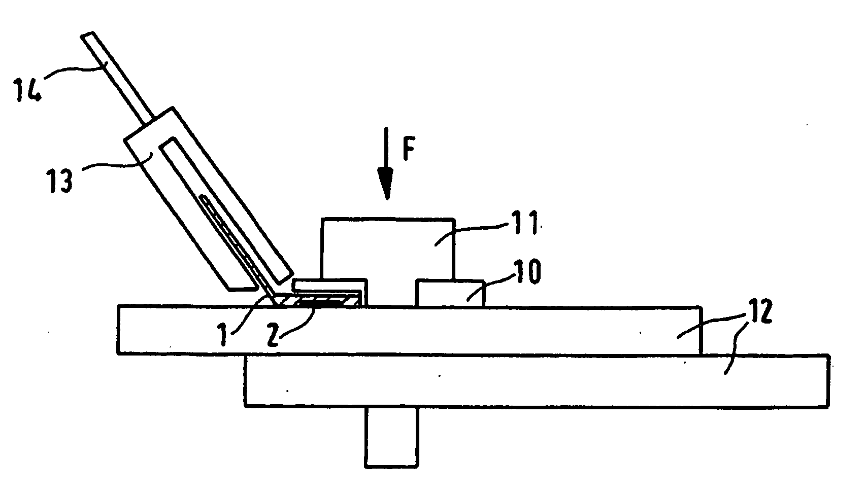
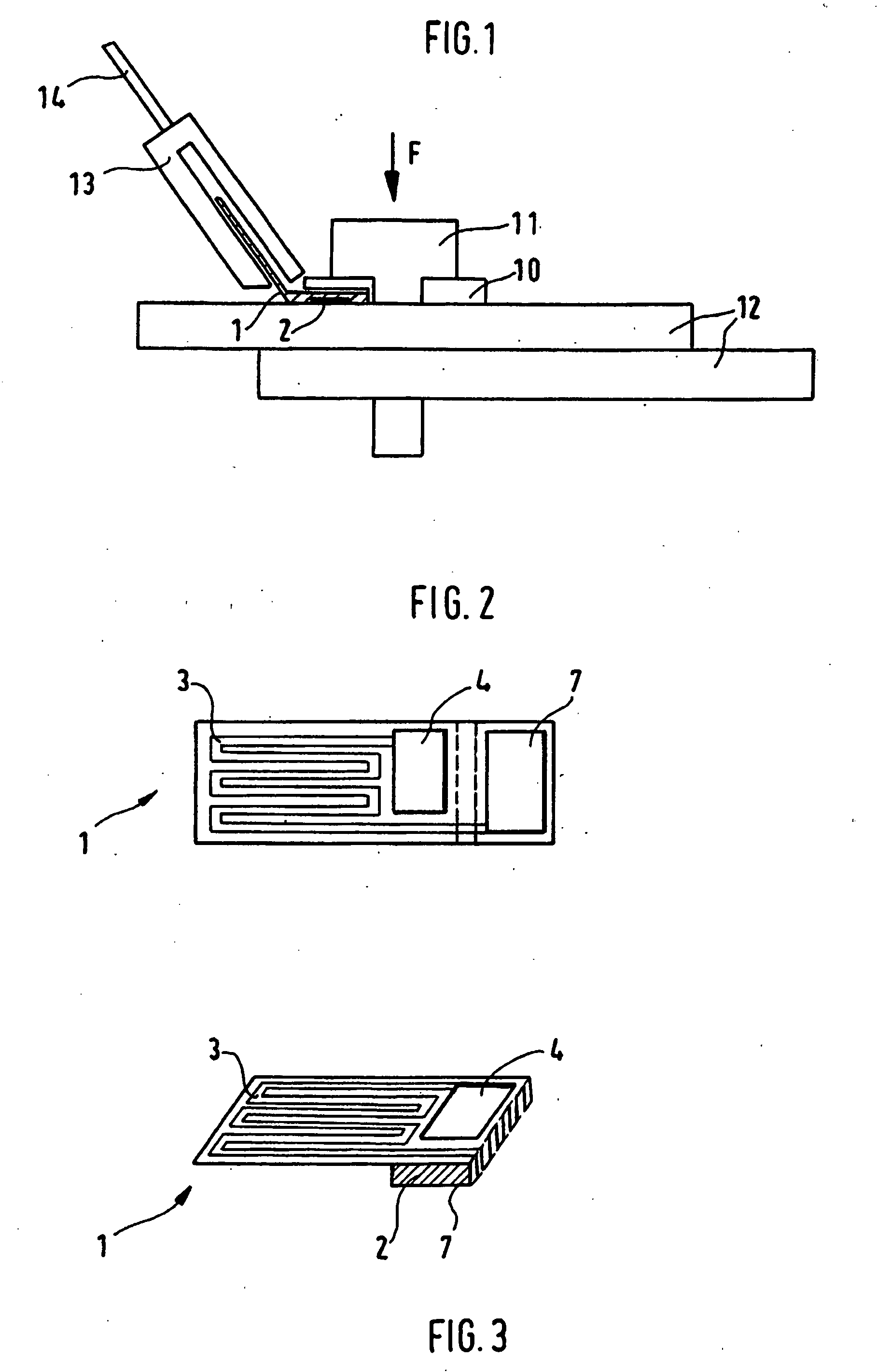
[0032]FIG. 1 shows a schematic representation of the sensor specified in the invention for determining the stress / strain conditions of a screwed bolt. In FIG. 1 the sensor is indicated by the number 1 and is integrated into a flat washer 10. The flat washer 10 with the integrated sensor 1, hereinafter also referred to as the modified flat washer, is positioned between a bolt 11 and a structure 12 that is connected to said bolt. Further, a testing device 13 (e.g. a transceiver) is coupled, contact-free, to the sensor 1, which will be described in greater detail further below. Via a data line 14 the data obtained from the transceiver are passed on to an evaluation unit (not illustrated here).

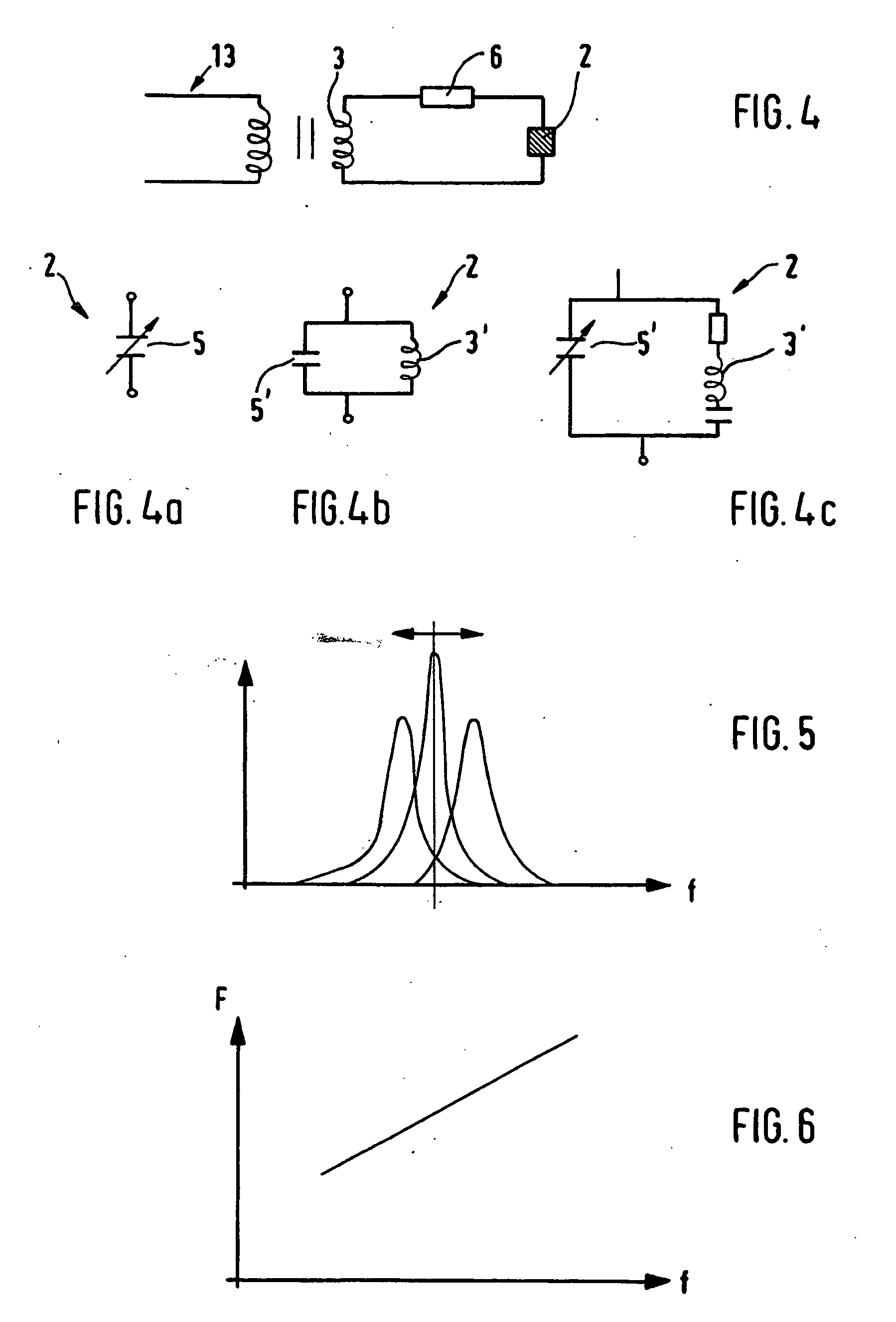
[0033] The sensor 1 comprises a dielectric, piezoelectric or magnetostrictive element 2, which is indicated only schematically in FIG. 1. In principle, materials with load- or pressure-dependent electromechanical couplings may be used. In FIG. 1 the element 2 is integrated into the flat washer 10...


PUM

PropertyMeasurementUnit
stress/strainaaaaaaaaaa
piezoelectricaaaaaaaaaa
magnetostrictiveaaaaaaaaaa

Abstract

A stress / strain measuring sensor for the continuous monitoring of stress / strain conditions, especially in screwed bolts, along with a corresponding measuring process is disclosed. An arrangement, and a corresponding method, are provided that are uncomplicated and easy to implement, and enable a continuous monitoring of stress / strain conditions. This is attained using a sensor (1) that comprises a first inductor (3) and at least one additional element (2), which comprises at least one pressure-dependent first impedance (5) or a second impedance (5′) and a second inductor (3′), wherein the second impedance (5′) and / or the second inductor (3′) are pressure-dependent, so that when the amount of pressure applied to the element (2) changes, the resonant frequency of an electromagnetic resonating circuit (3, 5; 3′, 5′) that is formed by impedance (5, 5′) and inductor (3, 3′) changes.

Description

BACKGROUND AND SUMMARY OF THE INVENTION [0001] The present invention relates to a stress / strain measuring sensor for the continuous monitoring of stress / strain conditions, especially in screwed bolts, and a corresponding measuring process. The invention is designed for use, for instance, in maintenance work for the purpose of checking stress / strain conditions so that, for example, torque levels of screwed bolts can be easily monitored and adjusted. [0002] In relation to this area of application, so-called torque keys are known from the state of the art, which operate, for example, using ultrasound sensors. [0003] Also known are stress sensors in which piezoelectric materials are used. In such cases, the known piezoelectric effect is utilized so that, when force is applied to the piezoelectric material via electric displacement, surface charges are created. A sensor of this type is described, for example, in WO 99 / 26046. [0004] The problem with this, however, is that the electrical c...

Claims


Application Information

Patent Timeline
Patent Type & Authority Applications(United States)
IPC IPC(8): G01L1/14G01L5/24
CPCG01L5/24G01L1/14
Inventor ZIMMERMAN, WERNERJANKER, PETER
Owner AIRBUS OPERATIONS GMBH
Why Eureka
Try Eureka