
Custom mouthguard

a mouthguard and custom technology, applied in the field of protective equipment, can solve the problems of degrading or preventing known mouthguards are often subjectively considered detrimental to dangers remain, so as to improve the retention, and improve the appearance of wearers. the effect of speech

Inactive Publication Date: 2005-12-29
AMBIS JR EDWARD J
View PDF13 Cites 51 Cited by
  • Summary
  • Abstract
  • Description
  • Claims
  • Application Information

AI Technical Summary

Benefits of technology

[0016] The present invention, in a first embodiment, is a heat and pressure formed custom mouthguard that protects maxillary and mandibular teeth, stabilizes temporomandibular joints, maximizes jaw muscle comfort and facilitates speech and breathing.
[0017] A mouthguard, according to the present invention, allows individuals wearing the mouthguard to speak easily and relatively naturally while still protecting their teeth and jaws and jaw joints. The ability to speak while wearing this mouthguard is due, in one aspect, to the relatively small size of the new mouthguard in comparison to known mouthguards. By using anatomical relationships heretofore ignored or discarded in known mouthguards, the mouthguard of the present invention allows for greater retention, stabilizes the temporomandibular joints, maximizes jaw muscle comfort and allows a wearer to speak easily. The upper anterior extent of the inventive mouthguard is matched with or generally level with the upper posterior extent. This anatomically matching relationship serves to maximize retentive fit on the teeth and soft tissue.
[0018] The mouthguard of the present invention is formed, in a preferred embodiment, through a combined use of heat and pressure about a dental cast or form that is largely representative of the maxillary anatomical structures that are to be protected. One preferred method of formation involves use of a machine such as a BioStar machine (available from Great Lakes Orthodontics of Buffalo, N.Y.) which machine heats a sheet of laminate thermoplastic material and pressure forms the heated sheet over a dental cast and into a close molded conformance therewith. Prior to such molding, the dental cast is modified to alter the resulting shape of the sheet being molded or formed. The sheet is subsequently trimmed to discard unwanted portions, thereby leaving a mouthguard of the present invention. The resultant mouthguard is extremely close fitting or conforming to certain teeth and portions of the maxilla. This close fit, in turn, renders the mouthguard of the present invention extremely retentive. One modification of the dental cast creates a significant or key structure of the mouthguard that further enhances its retentive property once fitted to the wearer. The dental cast is made of dental stone material. The modification of the dental cast removes a small portion of dental stone material in certain regions of the dental cast. In turn, this small portion of removed material eventually results in a mouthguard that is functionally and effectively more closely in contact with portions or regions of the wearer's mouth. That is, the resulting mouthguard is resiliently contacting the tissue within the wearer's mouth; and most specifically the mouthguard is resiliently contacting the wearer's mouth, including intaglio surfaces, with portions of the mouthguard that are the direct result of the modification to the dental cast. This added retention makes speaking and / or breathing easy and relatively natural for a wearer of the inventive mouthguard. A second modification alters the shape of the dental cast by removing a portion of the dental cast corresponding to the hard palate; in particular a portion posterior to the section that will be used to form or mold the sheet material to form the inventive mouthguard is removed.

Problems solved by technology

In general, known mouthguards share characteristic deficiencies in comfort afforded a wearer.
Known mouthguards typically degrade or impede a wearer's breathing and / or speech.
Moreover, known mouthguards are often subjectively considered detrimental to the appearance of wearers.
While those potential wearers may be temporarily compelled to wear such protective equipment when under the supervision of an authority figure, they often discard, lose, hide or otherwise avoid wearing such protective equipment within moments after their supervision is relaxed or terminated.
Unfortunately, the dangers remain and too often, teeth are then damaged or lost.
Preferrably, such a mouthguard would not render the wearer less attractive.

Method used


Image

  • Custom mouthguard
  • Custom mouthguard
  • Custom mouthguard

Examples


Embodiment Construction

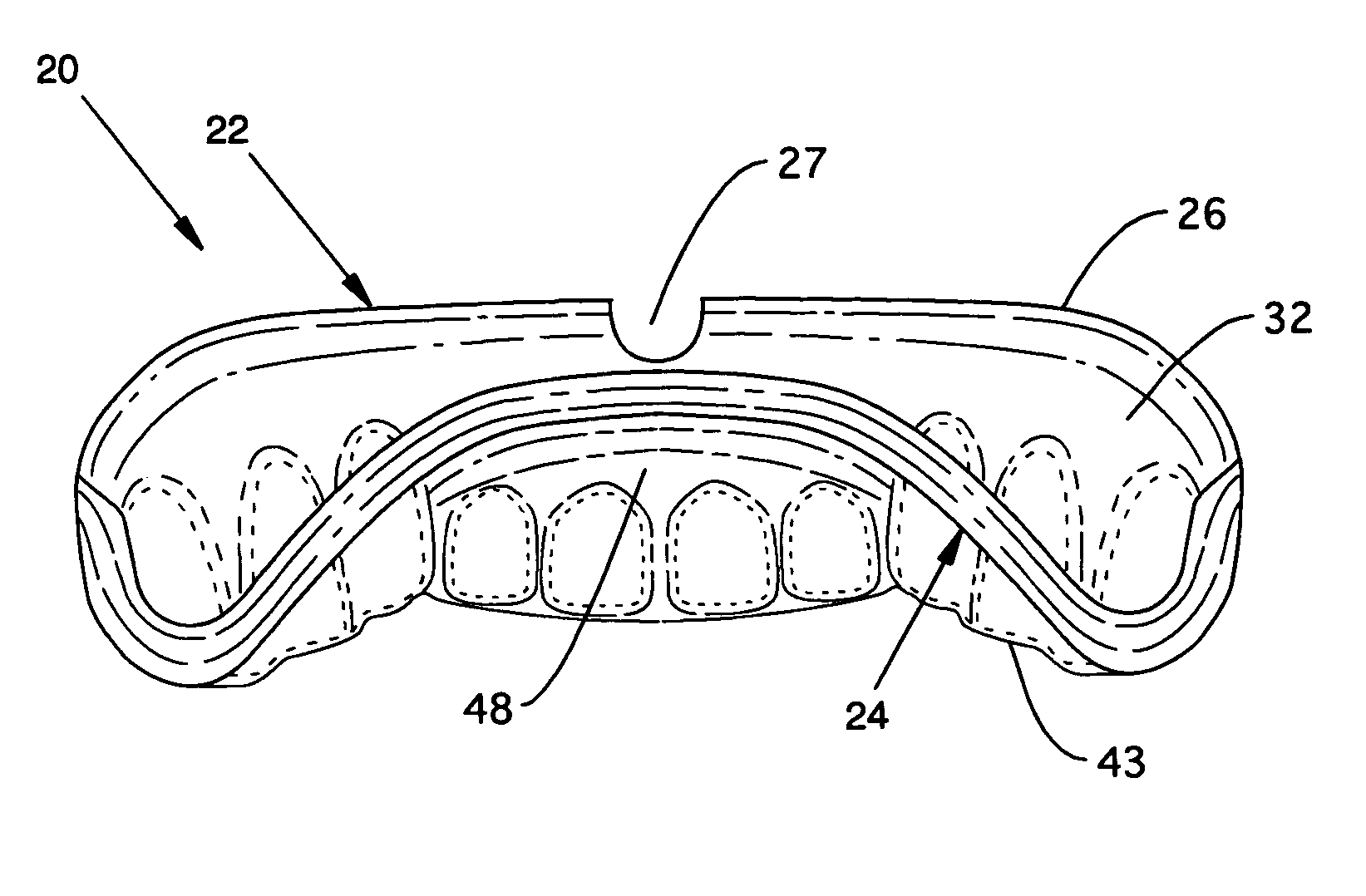
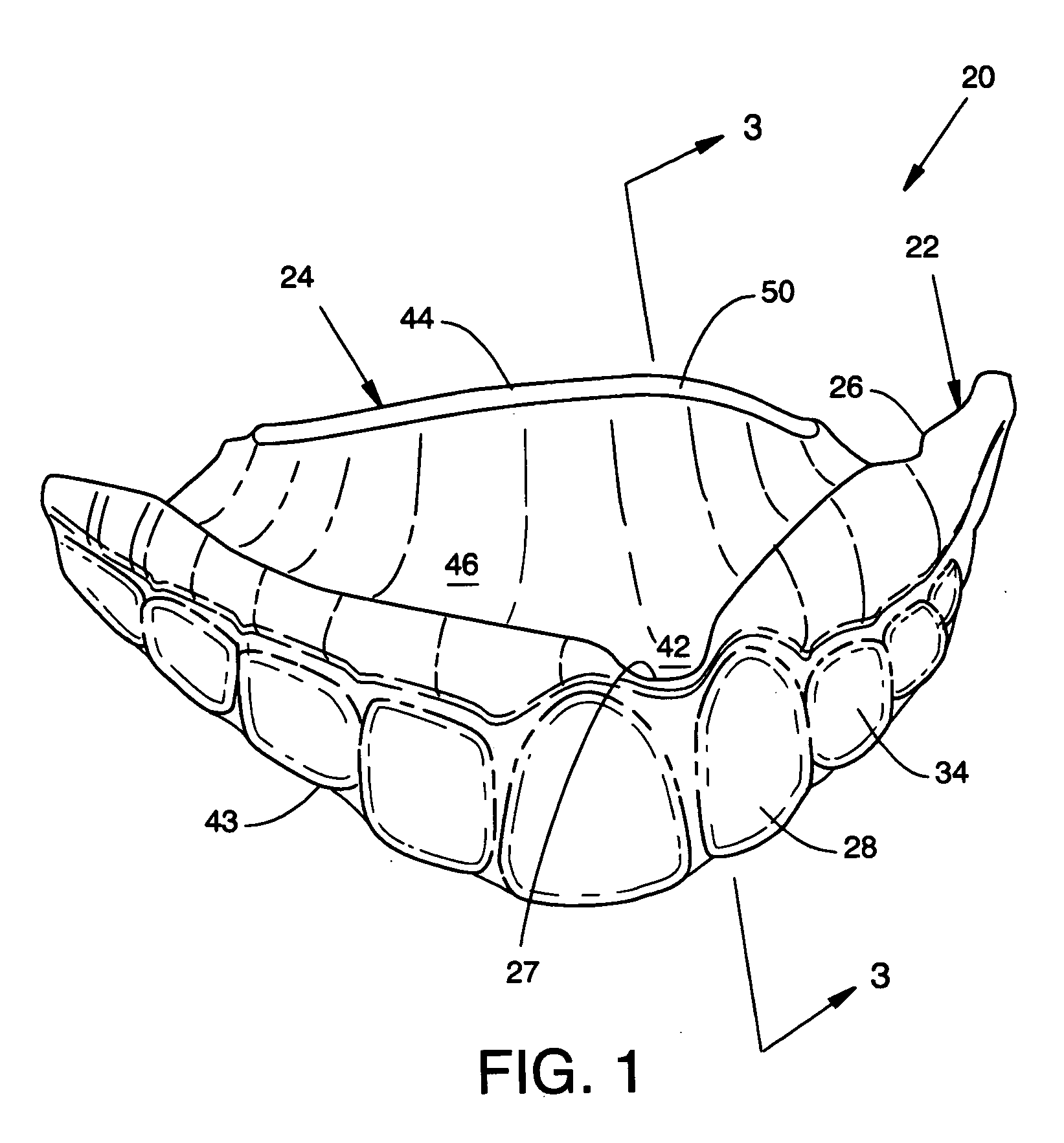
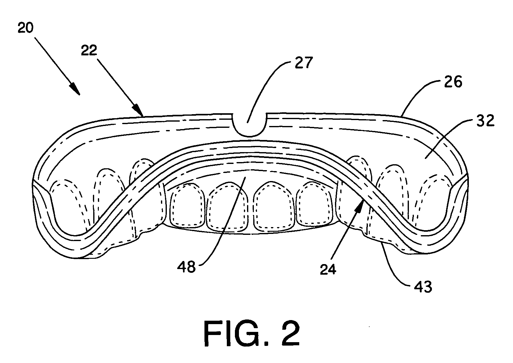
[0033] In a first embodiment, the present invention is a mouthguard 20, as shown in FIG. 1. The mouthguard 20 includes an anterior portion or wall 22 and a posterior portion or wall 24. The anterior wall 22 has an upper edge or extent 26 and a lower portion 28. A slight dip or notch 27 is centered on the upper extent 26 of anterior wall 22. The notch 27 accommodates the frenum (or frenulum) of the wearer, thereby allowing portions of the anterior wall 22 to reach higher on the gum 60 (as shown in FIG. 3). The anterior wall 22 has a curved shape and is adapted and custom fit and shaped for close conformance to the forward surfaces of the maxillary anterior teeth and gingival tissue of a wearer of the mouthguard 20. In particular, the anterior wall 22 has an inwardly directed surface 32 (perhaps best viewed in FIG. 2) which is adapted and shaped to contact the forward surfaces of the wearer's anterior teeth and gingiva and gums. The anterior wall 22 also has an outwardly directed surf...


PUM


Abstract

A custom mouthguard has a resilient U-shaped body with an anterior wall and a posterior wall. A post dam on the posterior wall forms a seal with palatal tissue to increase retention of the mouthguard in a wearer's mouth. The increased retention allows a wearer to speak and open mouth breath while wearing the mouthguarrd. The mouth guard also has an indexed region that serves to mutually stabilize maxillary teeth, mandibular teeth, mandible and TMJ components. Mouthguard methods and processes are also disclosed.

Description

BACKGROUND OF INVENTION [0001] The present invention relates to protective equipment, and, in particular, relates to protective equipment for human teeth. [0002] Mouthguards and related teeth protective equipment have been known since approximately the year 1900. (Scott, J., Burke, F. J. T. and Watts, D. C.; Br Dent J. 1994; 176: 310-314). In general, known mouthguards share characteristic deficiencies in comfort afforded a wearer. (DeYoung, Amy Kay, Robinson, Emerson and Goodwin, William C. JADA, v. 125, August, 1994, pp. 1112-1117. Woodmansey, Karl F. General Dentistry, January-February 1999, pp. 64-69.) Known mouthguards typically degrade or impede a wearer's breathing and / or speech. Moreover, known mouthguards are often subjectively considered detrimental to the appearance of wearers. [0003] One consequence of these characteristic shortcomings is a nearly universal disdain and avoidance of use by those potential wearers who are most likely to benefit from such protective equipme...

Claims


Application Information

Patent Timeline
IPC IPC(8): A61C5/14A63B71/08
CPCA63B71/085
Inventor AMBIS, EDWARD J. JR.
Owner AMBIS JR EDWARD J
Learn More