Cordless, self-contained, handheld spray gun

Inactive Publication Date: 2005-12-29
JUST A SIMPLE THING
View PDF14 Cites 67 Cited by
  • Summary
  • Abstract
  • Description
  • Claims
  • Application Information

AI Technical Summary

Benefits of technology

[0007]FIG. 2 depicts a cut-away side view of the cordless,

Problems solved by technology

There are certain disadvantages and limitations associated with using these conventional paint systems.
The primary disadvantage is that the spray g

Method used


Image

  • Cordless, self-contained, handheld spray gun
  • Cordless, self-contained, handheld spray gun
  • Cordless, self-contained, handheld spray gun

Examples


Embodiment Construction

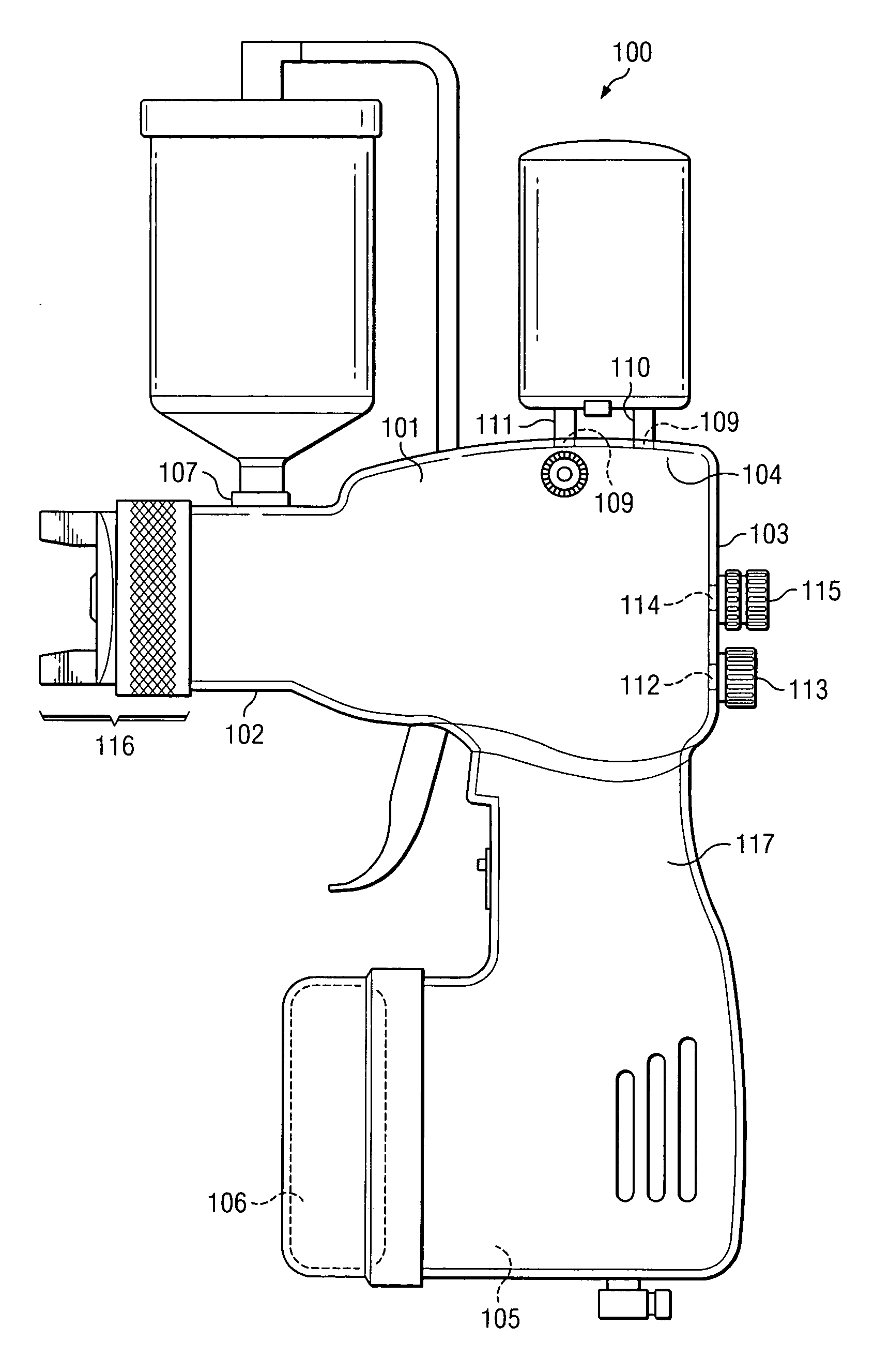
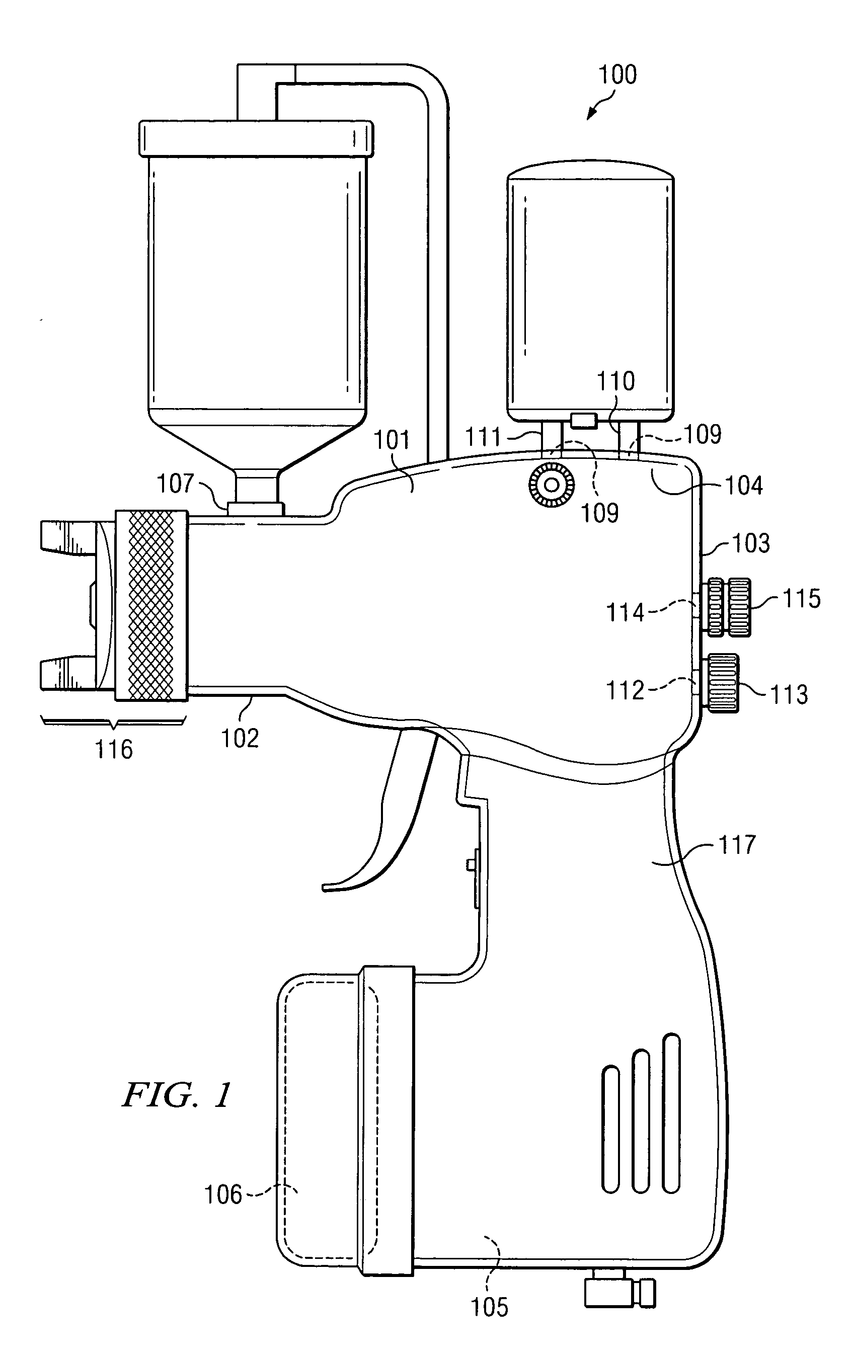
[0008] As seen in FIG. 1, the cordless, self-contained, handheld spray gun of the present invention has a typical gun body shape. More specifically, gun body 100 has a barrel portion 101 defined by a longitudinal first end 102 a longitudinal second end 103, a lateral first end 104 and lateral second end 105. Lateral second end 105 has a base portion adapted to receive a source of power, such as a battery 106. Also formed in gun body 100 is a paint container bore 107 proximate the longitudinal first end 102 through which an end of a paint container 108 is disposed, and air reservoir bores 109 through which air reservoir inlet 110 and air reservoir outlet 111 are disposed. Further formed in gun body 100 is fan control bore 112 through which fan control knob 113 is disposed and fluid control bore 114 through which fluid control mechanism 115 is disposed. A fluid nozzle assembly 116 is formed at, and coupled to, the end of longitudinal first end 102. Fluid nozzle assembly 116 can be ada...


PUM


Abstract

What is disclosed is a self contained, cordless, handheld spray gun (100). The spray gun (100) comprises a fluid container (225) in intercommunication with at least one fluid nozzle orifice (201) and a source of pressurized gas (204) in intercommunication with at least one gas nozzle orifice 207 and one fan nozzle orifice (227). The spray gun (100) is actuated by pulling a trigger (231) that opens at least one valve (202) so that the fluid, such as paint, primer, stain, varnish, sealant or the like, can flow to a fluid chamber (206), atomized, and sprayed through a fluid nozzle orifice (201) out onto the article to be painted.

Description

FIELD OF THE INVENTION [0001] The present invention generally pertains to spray guns and related devices adapted to spray fluids, such as paints, primers, stains, varnishes, sealants and the like. More specifically, but without restriction to the particular embodiment and / or use which is shown and described for purposes of illustration, the present invention relates to a cordless, self-contained, handheld spray gun. BACKGROUND OF THE INVENTION [0002] Electrically and pneumatically driven compressed air spray paint guns are well known. Such spray guns are used in the efficient painting of articles. These conventional spray paint guns are typically part of a painting system. These painting systems may include a tank or container in which the paint is stored and a pump which compresses air and delivers the air through a hose to the spray paint gun wherein the compressed air atomizes and forces the paint through a nozzle. Typically, the paint containers are located below the paint gun a...

Claims


Application Information

Patent Timeline
IPC IPC(8): B05B7/02B05B7/06B05B7/08B05B7/24B05B9/01B05B9/04
CPCB05B7/066B05B7/0815B05B7/241B05B7/2416B05B7/2437B05B7/2478Y10S239/14
Inventor REEDY, TONY
Owner JUST A SIMPLE THING
Why Eureka
Try Eureka