Hydro turbine generator

a technology of hydro turbines and generators, applied in the direction of motors, dynamo-electric machines, engine fuctions, etc., can solve the problems of affecting the approach, requiring significant infrastructure and damning, and affecting the tidal dynamics, so as to minimize downstream efficiency losses, reduce the effect of swirl losses, and stable and efficien

Inactive Publication Date: 2005-12-29
CLEAN CURRENT PARTNERSHIP
View PDF51 Cites 166 Cited by
  • Summary
  • Abstract
  • Description
  • Claims
  • Application Information

AI Technical Summary

Benefits of technology

[0021] The varies may be fixed or they may flip between a first and second position, the first position being appropriate for redirecting an inflow and the second position appropriate for redirecting an outflow to minimize downstream efficiency losses.
[0022] Another object of the present invention is to provide a bi-directional turbine with dual counter-rotating rotor disks to create a stable, efficient

Problems solved by technology

The Normandy and Nova Scotia projects required significant infrastructure and damning of tidal estuaries.
The effect of all such projects on the ocean inlet and estuaries is to interfere with tidal dynamics and disrupt marine biological ecosystems in the inter-tidal zones behind the dam.
While the pilot projects in Normandy and Nova Scotia are still in operation, they have not proven to be economical, and with the global rise in environmental consciousness, this approach has fallen into disfavor.
It is very difficult to maintain

Method used


Image

  • Hydro turbine generator
  • Hydro turbine generator
  • Hydro turbine generator

Examples


Embodiment Construction

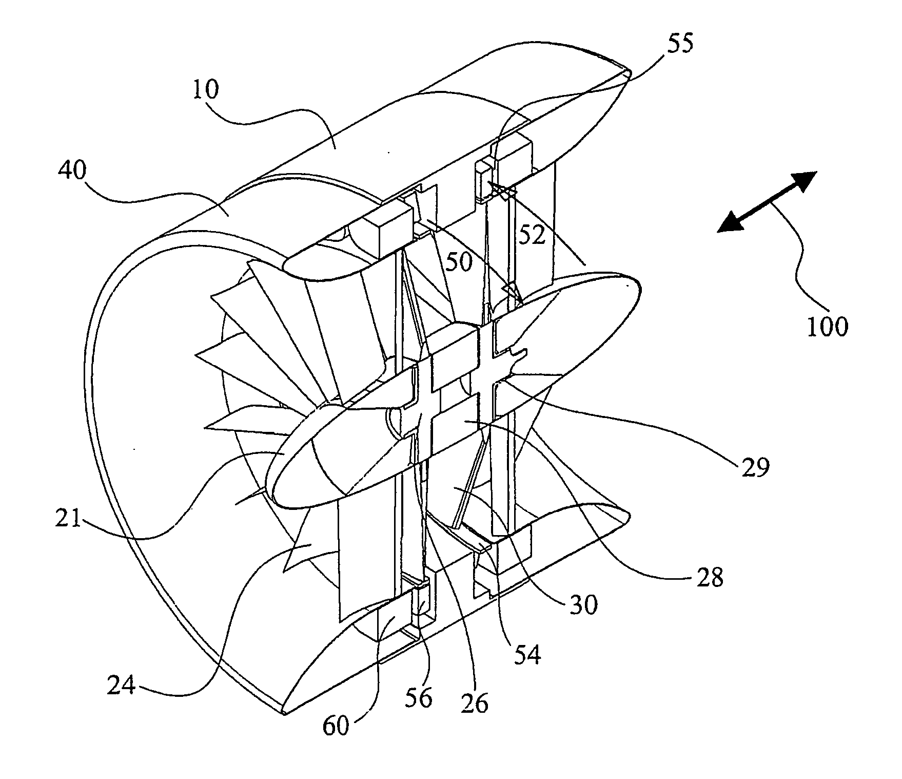
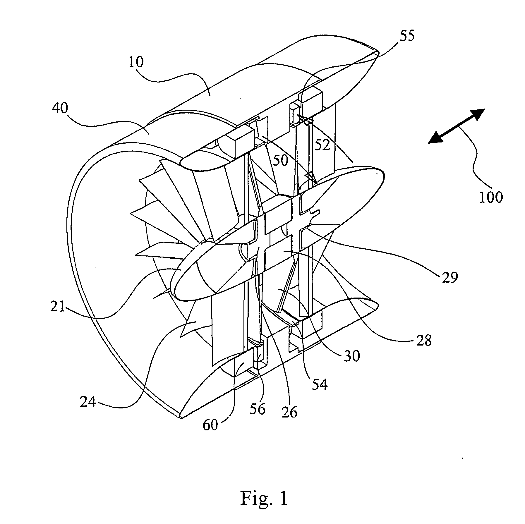
[0060] Referring to FIG. 1, a cut-away view of the preferred embodiment of the invention is shown. The modular ducted turbine generator unit 10 may be used as a single turbine generator unit 10 or with a plurality of turbine generator units 10, typically deployed in sub-sea tidal areas, although the design may be used in other environments such as rivers, tail-races or wind energy units. The purpose of the turbine generator unit 10 is to efficiently generate electrical power using tidal forces with minimal environmental impact. The preferred embodiment is intended for sub-sea deployment. It will be apparent that the present invention provides an efficient power generator unit with minimal moving parts.

[0061] The turbine generator unit 10 has two ends about a center line which are symmetrical. A hub 20 with an axis substantially parallel to the direction of water flow 100 is disposed along the central axis of the turbine generator 10. The hub 20 has a hub nose 21 at each end which m...


PUM


Abstract

An apparatus is disclosed for a turbine for generating electrical power from water or air flow comprising at least one rotor disk having a plurality of hydrofoil blades, a guide vanes, a cylindrical housing, and a generator means. A rim generator comprising a magnet race rotor rim and fixed stator coils in the housing is used. The apparatus is fitted with a screen to stop the ingress of debris and marine life, and a skirt augmenter device to reduce the Betz effect. The apparatus is preferably for sub-sea deployment and driven by tidal currents, but may be powered by river current or wave driven air or by wind. The apparatus may be deployed on at least one telescoping pole, tethered to the sea-bed and kept buoyant by buoyant concrete in the housing, inserted in a dam, under a barge or in a tidal power array.

Description

1. TECHNICAL FIELD [0001] The present invention relates generally to hydrokinetic electrical power generating turbines and methods of use and deployment. More specifically, a ducted rim type generator, bi-directional turbine for generating power from tidal currents in various deployments is disclosed. 2. BACKGROUND OF THE INVENTION [0002] Tidal power has been harnessed for many centuries. Tidal grain mills have been located on coastal inlets where seawater could be trapped by sluice gates in low dams at high tide, to be released through a mill wheel at low tide. Such mill wheels are examples of rudimentary hydraulic turbines. [0003] Energy shortages have spurred research activity, including the construction of significant pilot projects in the area of tidal power generation using more modern turbine designs, in Normandy, France and Nova Scotia, Canada. The Normandy and Nova Scotia projects required significant infrastructure and damning of tidal estuaries. The effect of all such pro...

Claims


Application Information

Patent Timeline
IPC IPC(8): F03B3/12F03B3/18F03B3/04F03B11/08F03B13/00F03B13/08F03B13/10F03B13/26F03B17/06F03D1/00H02K7/18H02K16/00H02P9/04
CPCF03B3/128Y02E10/28F03B13/10F03B13/264F03B17/061F05B2210/16F05B2210/404F05B2220/7066F05B2220/7068F05B2240/133F05B2240/93F05B2240/97F05B2260/63Y02E10/223F03B13/083Y02E10/20Y02E10/30F03B17/06
Inventor DAVIS, BARRY V.GRILLOS, EMMANUELALLISON, STEPHEN
Owner CLEAN CURRENT PARTNERSHIP
Why Eureka
Try Eureka