
Battery with non-volatile memory for LMR portable radio applications

Active Publication Date: 2005-12-29
EAGLE TECH LLC
View PDF1 Cites 18 Cited by
  • Summary
  • Abstract
  • Description
  • Claims
  • Application Information

AI Technical Summary

Benefits of technology

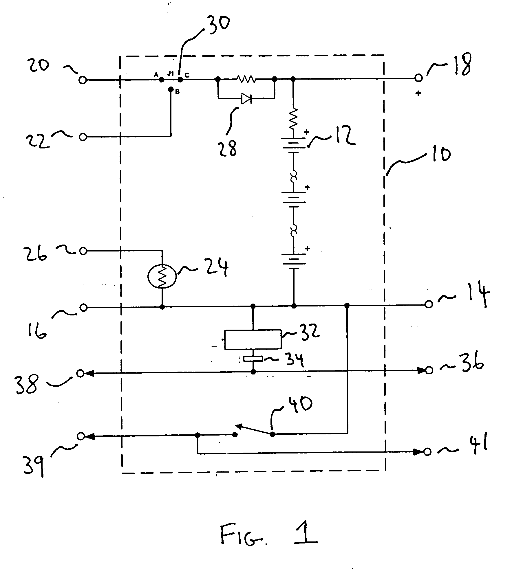
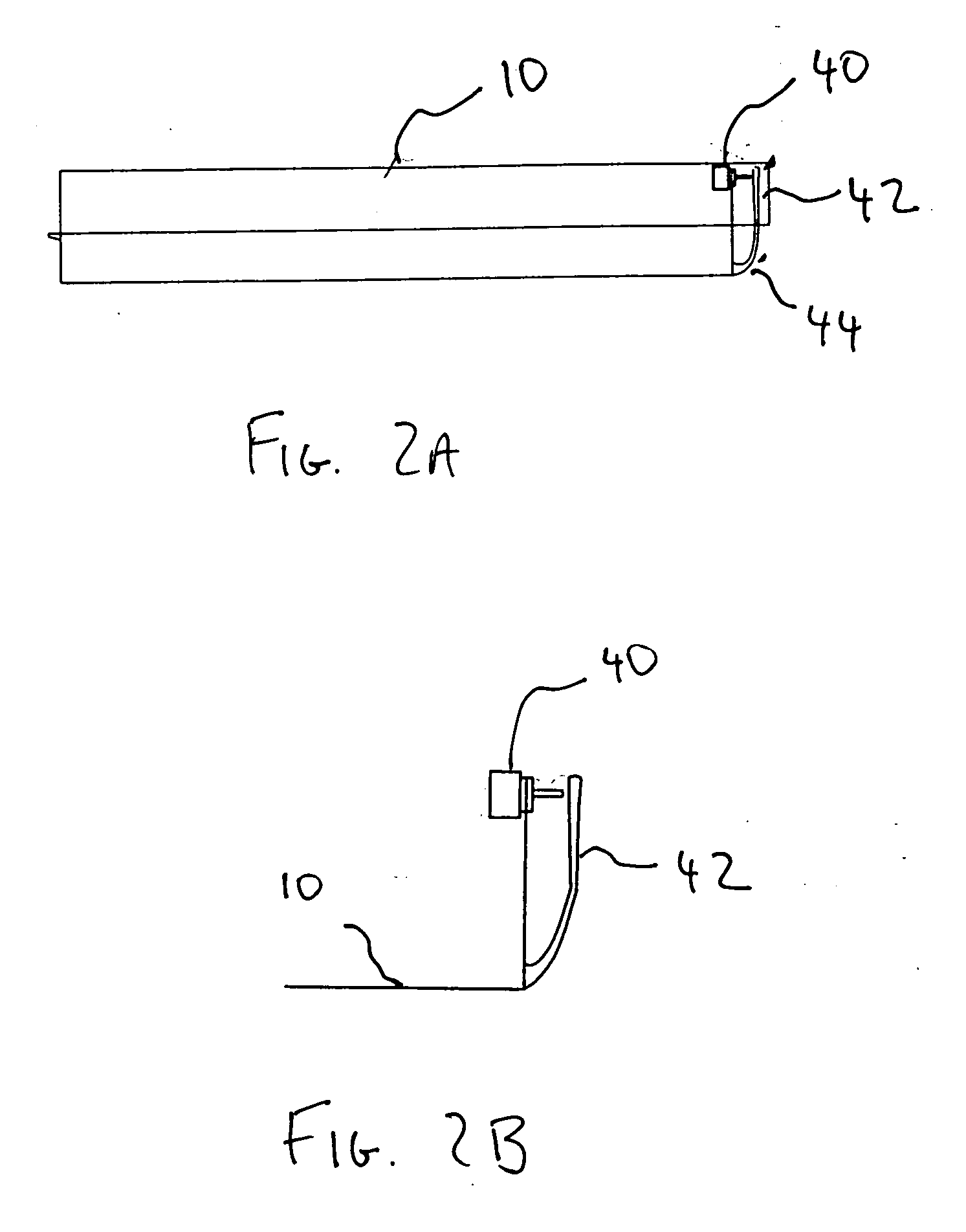
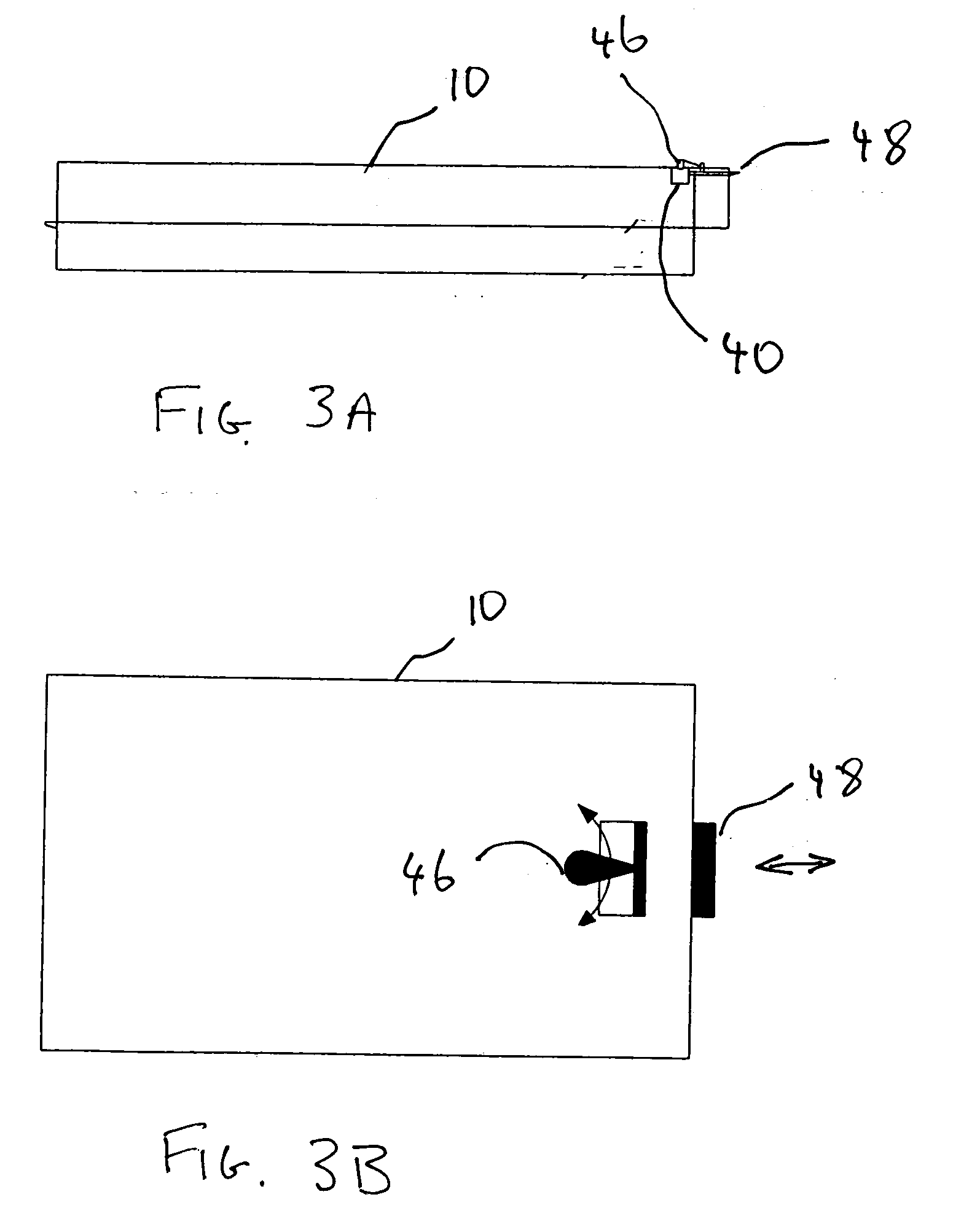
[0009] The battery pack may also have a latch, which has to be released in order to remove the battery pack from any device to which it can be functionally connected. In a preferred embodiment, the action of releasing the latch may cause a final battery status to be written to the non-volatile memory. Releasing the latch may, for instance, close a data-write switch, thereby triggering a data write just before the battery pack is removed from the device. In this way, the memory may be assured of having up-to-date battery status information, no matter when the removal occurs in relation to any scheduled data writes. This eliminates the need to schedule frequent data writes, thus minimizing power drainage, and considerably lengthening the time to failure of the non-volatile memory, which typically occurs after about 50,000 write cycles.

Problems solved by technology

Nickel cadmium (NiCd), and to a lesser extent nickel metal hydride (NiMH), rechargeable batteries also suffer from “voltage depression”, an affect in which the battery voltage drops unusually quickly if they are recharged before being fully discharged.
Certain Land Mobile Radio (LMR) portable radio applications, however, have battery monitoring requirements that go beyond what is provided by current smart rechargeable battery technology.
Attempting to meet these stringent requirements results in conflicting technology needs.
The problem with this solution is that, to meet the low cost, long term storage requirements, the most suitable memory is an Electrically Erasable Programmable Read Only Memory (EEPROM) device, but EEPROMs have a finite number of erase / write cycles (typically 50,000) before they fail.
(The erase function degrades an oxide barrier on the silicon and eventually leads to failure of the EEPROM).

Method used


Image

  • Battery with non-volatile memory for LMR portable radio applications
  • Battery with non-volatile memory for LMR portable radio applications
  • Battery with non-volatile memory for LMR portable radio applications

Examples


Embodiment Construction

[0015] The present invention relates to systems and methods that monitor and record rechargeable battery status and history. In particular, the present invention relates to such systems and methods that meet the stringent demands of industrial and professional users such as, but not limited to, emergency and rescue services which use rechargeable batteries to power devices such as, but not limited to portable radios. Such users require that any technology added to the rechargeable batteries used in, for instance, their LMR portable radios, has no detrimental impact on the battery, even during prolonged storage of the battery packs for as long as five years. This means that the battery status technology must provide data retention for up to five years with out power and under all required environmental conditions.

[0016] Industrial and professional users also require that any status technology must not affect the battery pack performance or specifications. The technology must also be...


PUM


Abstract

An apparatus and method for monitoring and storing a status of a rechargeable battery pack in which the battery pack status is monitored by a device while the battery pack is functionally connected to that device, and then periodically updated to a non-volatile memory in the battery pack. The non-volatile memory may be connected in power isolation from the rechargeable cells, thereby ensuring that the battery is not drained during long periods of storage. The battery pack may also have a latch, which has to be released in order to remove the battery pack from any device to which it can be functionally connected. Releasing the latch may cause the battery status to be written to the non-volatile memory, ensuring that the battery's memory has up-to-date battery status information, whenever the battery is removed from the device regardless of any scheduled data writes.

Description

FIELD OF THE INVENTION [0001] The present invention relates to rechargeable battery technology and, more particularly, to methods and apparatus for in-battery storage of information relating to battery charge and life-cycle status. BACKGROUND OF THE INVENTION [0002] Rechargable batteries are used extensively to power portable electronic devices such as portable or cellular phones and laptop computers. When using a device powered by a rechargeable battery, it is desirable to know how much usable charge remains in the battery. As the capacity of a rechargeable battery diminishes with each recharging cycle, accurately predicting the remaining charge requires knowing how many times the battery has been recharged. Nickel cadmium (NiCd), and to a lesser extent nickel metal hydride (NiMH), rechargeable batteries also suffer from “voltage depression”, an affect in which the battery voltage drops unusually quickly if they are recharged before being fully discharged. For optimum recharging of...

Claims


Application Information

Patent Timeline
IPC IPC(8): H01M10/42H02J7/00
CPCH01M10/4207H01M10/4285H01M10/425Y02E60/10
Inventor GRUNERT, DAVID R.MILLER, SHANE
Owner EAGLE TECH LLC
Learn More