DC relay

Inactive Publication Date: 2005-12-29
SUMITOMO ELECTRIC IND LTD
View PDF8 Cites 16 Cited by
  • Summary
  • Abstract
  • Description
  • Claims
  • Application Information

AI Technical Summary

Benefits of technology

[0077] In the case where contact pairs are arranged so that they can be connected in series in a conducting state, division of the voltage between the contacts on a cutoff occasion allows the voltage to be cut off in a shorter time. As a result, damage of the contact through the arc current can be suppressed by reducing the voltage across the contacts.
[0078] By increasing the number of contacts and connecting these contacts in series, a hermetic structure of sealing the extinction gas is no longer required. Therefore, a direct current relay

Problems solved by technology

In such relays, the cut off speed is extremely low since the arc generated when the high direct current voltage is to be cut off is very large.
It was extremely difficult to achieve cut off in a short time.
This poses the problem that the entire relay is increased in size.
Furthermore, the cost of the relay will become high

Method used


Image

  • DC relay
  • DC relay
  • DC relay

Examples


first embodiment

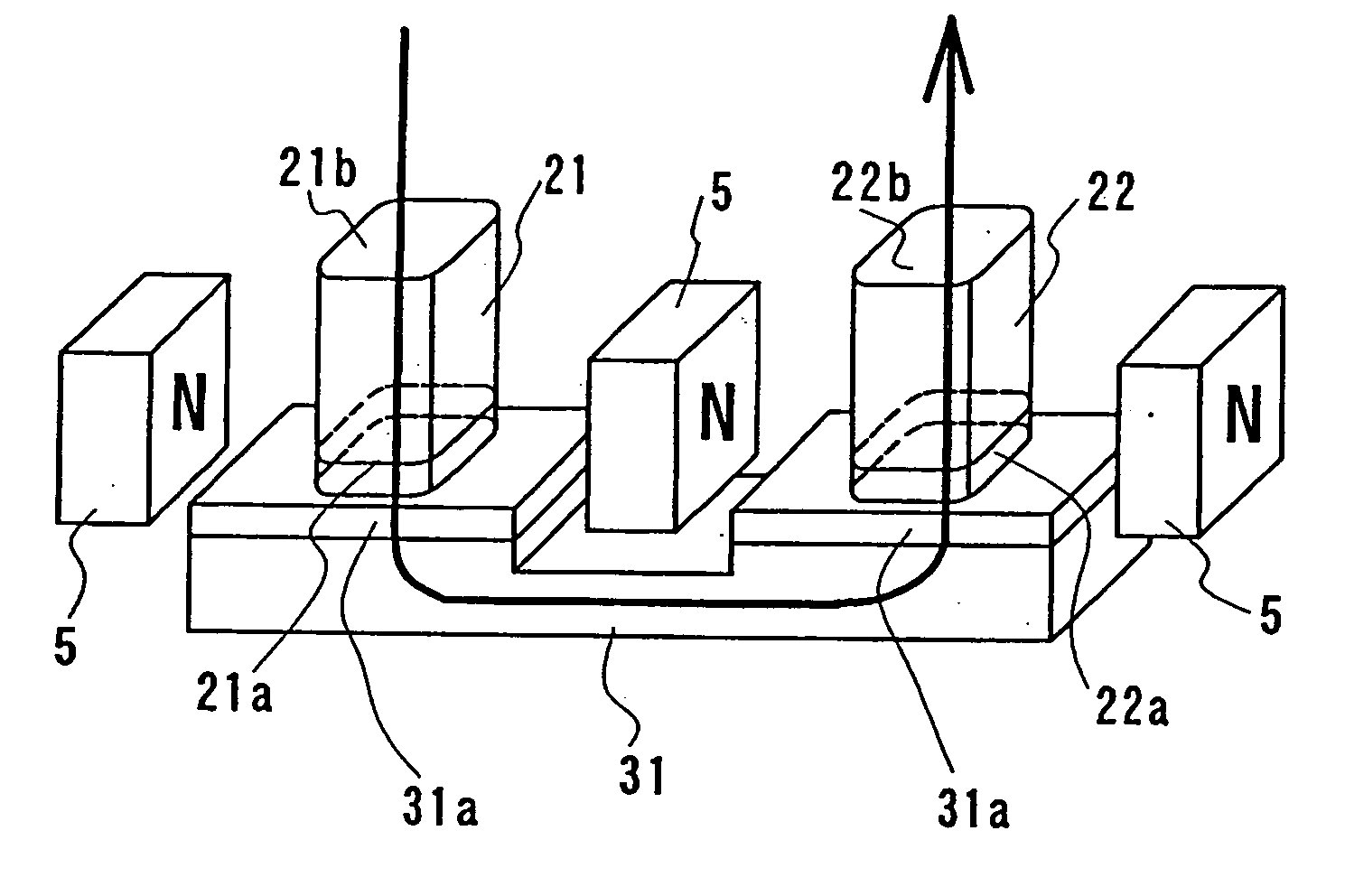
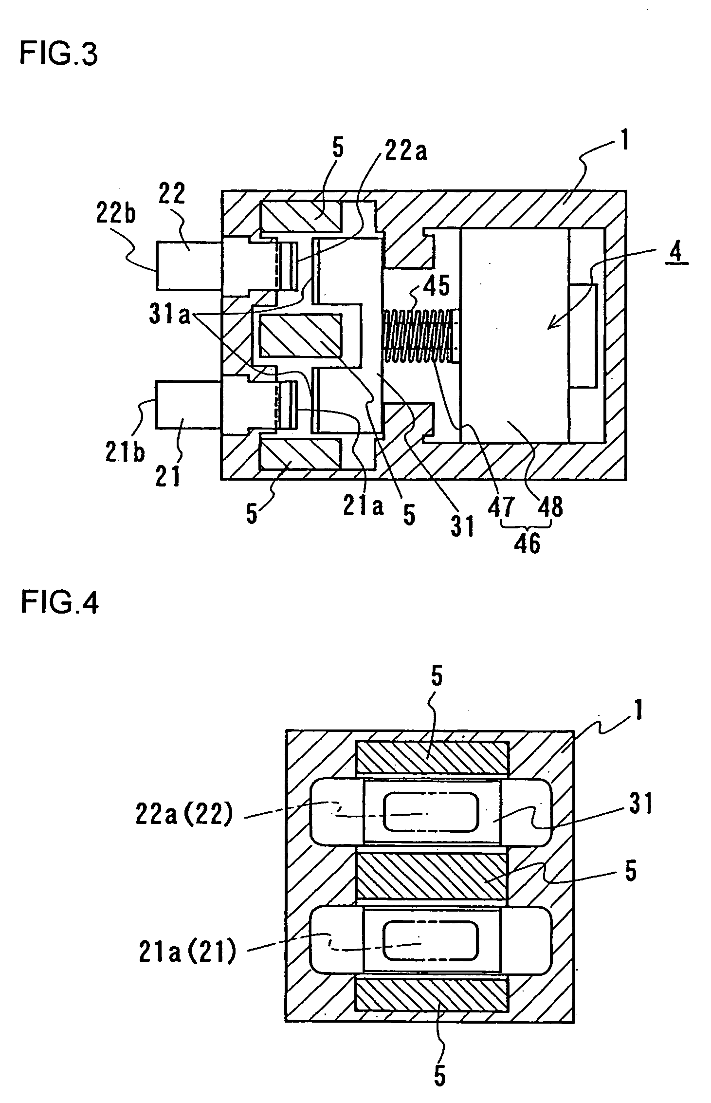
[0092] A direct current relay according to a first embodiment includes in a casing 1, as shown in FIG. 3, an input contact 21 and an output contact 22 that are stationary contacts, a linking contact 31 that is a movable contact, and a contact driving mechanism 4.

[0093] Input and output contacts 21 and 22 include contact regions 21a and 22a to be brought into contact with linking contact 31, and terminal connections 21b and 22b, respectively. An external terminal is connected to each of terminal connections 21b and 22b.

[0094] Linking contact 31 is U-shaped in cross section. The flat face at both sides of this U shape is identified as a contact region 31a. Contact region 31a of linking contact 31 is brought into contact with contact region 21a of input contact 21 and contact region 22a of output contact 22.

[0095] In the present embodiment, contact region 21a of input contact 21 and one contact region 31a of linking contact 31 constitute one contact pair, whereas contact region 22a ...

second embodiment

[0117] In the first embodiment, a direct current relay that can have contact pairs connected in series in a conducting state was described. The second embodiment is directed to allowing contact pairs to be connected in parallel in a conducting state.

[0118] As shown in FIGS. 5 and 6, the direct current relay according to the second embodiment includes an input contact 6 identified as a fixed contact, and an output contact 7 identified as a movable contact. Both input contact 6 and output contact 7 have an approximately U shape in cross section. The flat face at both sides of this U shape are identified as contact regions 61 and 71. Each of these contacts includes two contact regions 61 and 71. The two contact regions 61 of input contact 6 are brought into contact with two contact regions 71, respectively, of counter output contact 7.

[0119] In the present embodiment, one contact region 61 of input contact 6 and one contact region 71 of output contact 7 constitute one contact pair. T...

third embodiment

[0127] As shown in FIG. 9, a direct current relay according to a third embodiment includes, in casing 1, a plurality of stationary contacts 2, a plurality of movable contacts 3, and a contact driving mechanism 4.

[0128] Stationary contact 2 includes, as shown in FIG. 9, an input contact 21 to which an external terminal is connected, an output contact 22, and one intermediate contact 23 disposed between contacts 21 and 22.

[0129] Input contact 21 and output contact 22 include respective one of contact regions 21a and 22a to be brought into contact with movable contact 3, and terminal connections 21b and 22b, respectively. Terminal connections 21b and 22b protrude from casing 1.

[0130] Intermediate contact 23 has a U shape or a square bracket shape in cross section. A contact region 23a to be brought into contact with movable contact 3 is formed at each end side of the U shape. Although not shown, input contact 21, output contact 22 and intermediate contact 23 are secured in casing 1 ...


PUM


Abstract

A direct current relay includes a plurality of contact pairs, and a plurality of magnets (5). Each of the plurality of contact pairs is configured having contacts (21, 22, 31) with contact regions (21a, 22a, 31a) disposed to allow opening and closure with respect to each other. The plurality of contact pairs are disposed such that the plurality of magnets (5) are disposed on one straight line, and the contact pairs are located between the magnets (5) on a line identical to the straight line. Each of the plurality of magnets (5) is provided to distort an arc generated between contacts (21, 22, 23, 31) on an occasion of relay cut off in a direction crossing the straight line. Even if a backward current flows, arcs will not interfere with each other, allowing extinguishing in a short time. Accordingly, a direct current relay can be obtained, capable of cutting off a high direct current voltage in a short time even on an occasion of backward current while minimizing the number of magnets and allowing down-sizing with a simple structure.

Description

TECHNICAL FIELD [0001] The present invention relates to a direct current relay. Particularly, the present invention relates to a direct current relay that can reliably cut off direct current by inhibiting interference between arcs generated at a plurality of pairs of contacts, when provided. BACKGROUND ART [0002] Recently, vehicles of high voltage (approximately 300V) such as hybrid vehicles and fuel-cell powered vehicles have been developed from the standpoint of environmental issues. Such vehicles include a control circuit constituted of a main battery of high direct current voltage and a high voltage circuit. In the case of an accident or the like, the battery must be disconnected from the control circuit since it corresponds to a high direct current voltage. To this end, a direct current relay formed of a mechanical contact is provided between the battery and the control circuit. [0003] In such relays, the cut off speed is extremely low since the arc generated when the high dire...

Claims


Application Information

Patent Timeline
IPC IPC(8): H01H1/023H01H1/06H01H9/44H01H50/00H01H50/54
CPCH01H9/443
Inventor IMANISHI, HIROYUKIYOSHIMURA, AKINOBUARIYOSHI, TAKESHITSURITA, TAMIONISHI, YASUHIKO
Owner SUMITOMO ELECTRIC IND LTD
Why Eureka
Try Eureka