System and method for mounting an image capture device on a flexible substrate

a flexible substrate and image capture technology, applied in the field of electronic devices, can solve the problems of reducing the precision with which the image capture device can be aligned with the opening in the camera, the manufacturing process and the quality of the device, and the inability to manufacture and manufacture the device, so as to facilitate the fast and efficient assembly of digital camera modules, reduce the tolerance of optical alignment related to the number of electrical connections, and facilitate the effect of fast and efficient assembly

Active Publication Date: 2005-12-29
NANCHANG O FILM OPTICAL ELECTRONICS TECH CO LTD
View PDF19 Cites 149 Cited by
  • Summary
  • Abstract
  • Description
  • Claims
  • Application Information

AI Technical Summary

Benefits of technology

[0011] The present invention overcomes the problems associated with the prior art by providing a digital camera module that includes an image capture device mounted on an FPC substrate. Mounting the image capture device on the FPC substrate greatly reduces optical alignment related tolerances and the number of electrical connections, as compared to devices of the prior art. The invention further facilitates the fast and efficient assembly of digital camera modules that can be easily aligned with other features of a digital camera.

Problems solved by technology

The devices and assembly methods of the prior art have several disadvantages in both the manufacturing process and the quality of the device.
Alignment of the image capture device with the opening in the camera can be difficult, particularly in small cameras (e.g., cameras in mobile telephones).
Because multiple devices are mounted on the PCB, the tolerances accumulate to reduce the precision with which the image capture device can be aligned with the opening.
Additionally, PCBs typically include other components (e.g., keypad, etc.) that must be aligned with other openings, further complicating the alignment problem.
Although the device of FIG. 1 helps alleviate the alignment problem, it creates other disadvantages.
Further, the additional components require additional assembly steps.
The cost of the additional components and the additional assembly steps increase the overall cost of the product.
Note also that camera module 100 includes an increased number of electrical connections and, therefore, has an increased number of points of possible failure.
The increased number of electrical connections, and thus the increased number of points of possible failure, decreases the overall reliability of the product.
Mounting the image capture device on the FPC substrate greatly reduces optical alignment related tolerances and the number of electrical connections, as compared to devices of the prior art.

Method used


Image

  • System and method for mounting an image capture device on a flexible substrate
  • System and method for mounting an image capture device on a flexible substrate
  • System and method for mounting an image capture device on a flexible substrate

Examples


Embodiment Construction

[0034] The present invention overcomes the problems associated with the prior art, by providing a system and method for mounting an image capture device on an FPC substrate. In the following description, numerous specific details are set forth (e.g., particular construction materials, FPC substrate structure, etc.) in order to provide a thorough understanding of the invention. Those skilled in the art will recognize, however, that the invention may be practiced apart from these specific details. In other instances, details of well known electronic manufacturing practices (e.g., material selection, assembly, focusing operations, etc.) and components have been omitted, so as not to unnecessarily obscure the present invention.

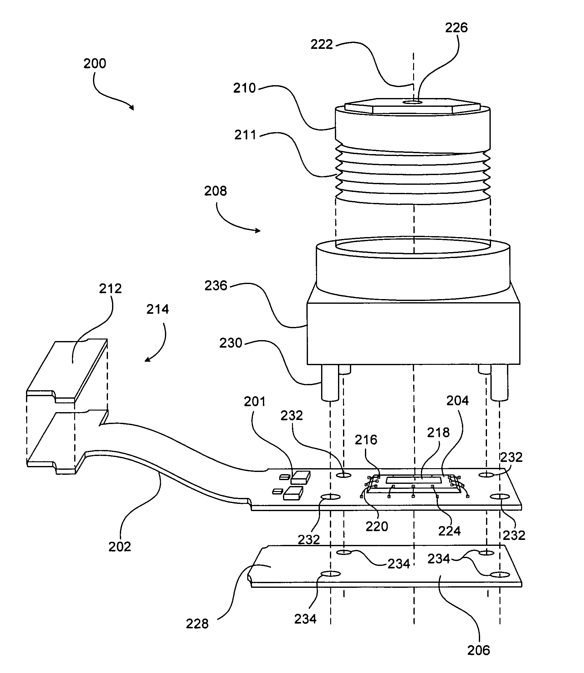
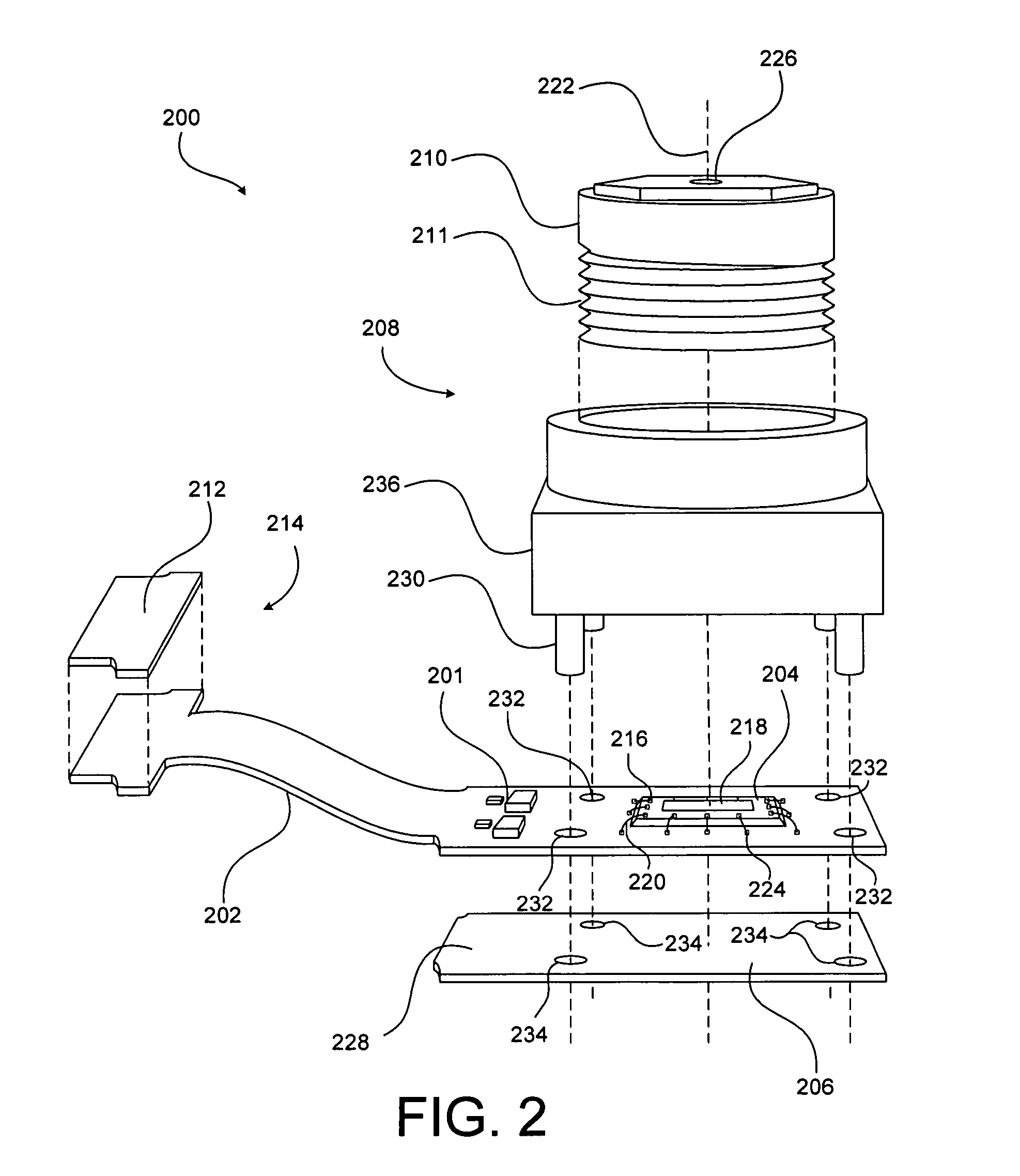
[0035]FIG. 2 is an exploded view of a digital camera module 200, which includes an image capture device 204, mounted directly to an FPC substrate 202. Digital camera module 200 further includes a lens housing 208 mounted to FPC substrate 202, and a connector 214 ...


PUM


Abstract

A digital camera module includes an image capture device mounted on a flexible circuit substrate. In one embodiment of the digital camera module, the image capture device is mounted directly (e.g., by an adhesive) on the flexible circuit substrate. A stiffener (e.g., a piece of circuit board material) is mounted to the back of the flexible circuit substrate to support wire bonding of the image capture device onto the flexible circuit substrate and/or to support the mounting of additional components (e.g., a lens housing).

Description

BACKGROUND OF THE INVENTION [0001] 1. Field of the Invention [0002] This invention relates generally to electronic devices, and more particularly to a device for mounting an image sensor. Even more particularly, the invention relates to a device for mounting an image sensor on a flexible substrate such as a flexible printed circuit (FPC). [0003] 2. Description of the Background Art [0004] Unlike traditional cameras that use film to capture and store an image, digital cameras use various solid-state devices collectively referred to as image capture devices. These small silicon chips contain millions of photosensitive diodes called photosites. When the shutter (mechanical or electrical) is open, each photosite records the intensity or brightness of the incident light by accumulating a charge; the more light, the higher the charge. The brightness recorded by each photosite is then stored as a value indicative of the brightness and / or color for a corresponding pixel of the captured imag...

Claims


Application Information

Patent Timeline
Patent Type & Authority Applications(United States)
IPC IPC(8): G06K9/00H01L27/00H01L27/14H01L27/146H04N5/225H05K1/18
CPCH01L27/14618H01L27/14625H01L2924/15192H04N5/2254H05K1/189H04N5/2253H01L27/14605H04N23/54H04N23/55
Inventor SINGH, HARPUNEETBRATHWAITE, NICHOLAS E.GRAYDON, BHRET R.
Owner NANCHANG O FILM OPTICAL ELECTRONICS TECH CO LTD
Why Eureka
Try Eureka