Dynamic current sharing dc-dc switching power supply

a technology of dc-dc switching power supply and dynamic current, which is applied in the direction of dc network circuit arrangement, dc source parallel operation, transportation and packaging, etc., can solve the problems of high current bus, circuit design dilemma, and high cost of circuits and devices

Active Publication Date: 2005-12-29
THE BOARD OF TRUSTEES OF THE UNIV OF ILLINOIS
View PDF4 Cites 44 Cited by
  • Summary
  • Abstract
  • Description
  • Claims
  • Application Information

AI Technical Summary

Problems solved by technology

This presents a dilemma in circuit design.
Delivering high current loads, e.g., hundreds of amps, to printed circuit boards and integrated circuit devices can raise the cost of circuits.
High current buses add significant expense to circuits and devices, but are generally necessary to deliver high current to printed circuit boards.
Success in this scheme requires current sharing among the parallel converters, as imperfect current sharing can result in the overloading of an individual converter.

Method used


Image

  • Dynamic current sharing dc-dc switching power supply
  • Dynamic current sharing dc-dc switching power supply
  • Dynamic current sharing dc-dc switching power supply

Examples


Embodiment Construction

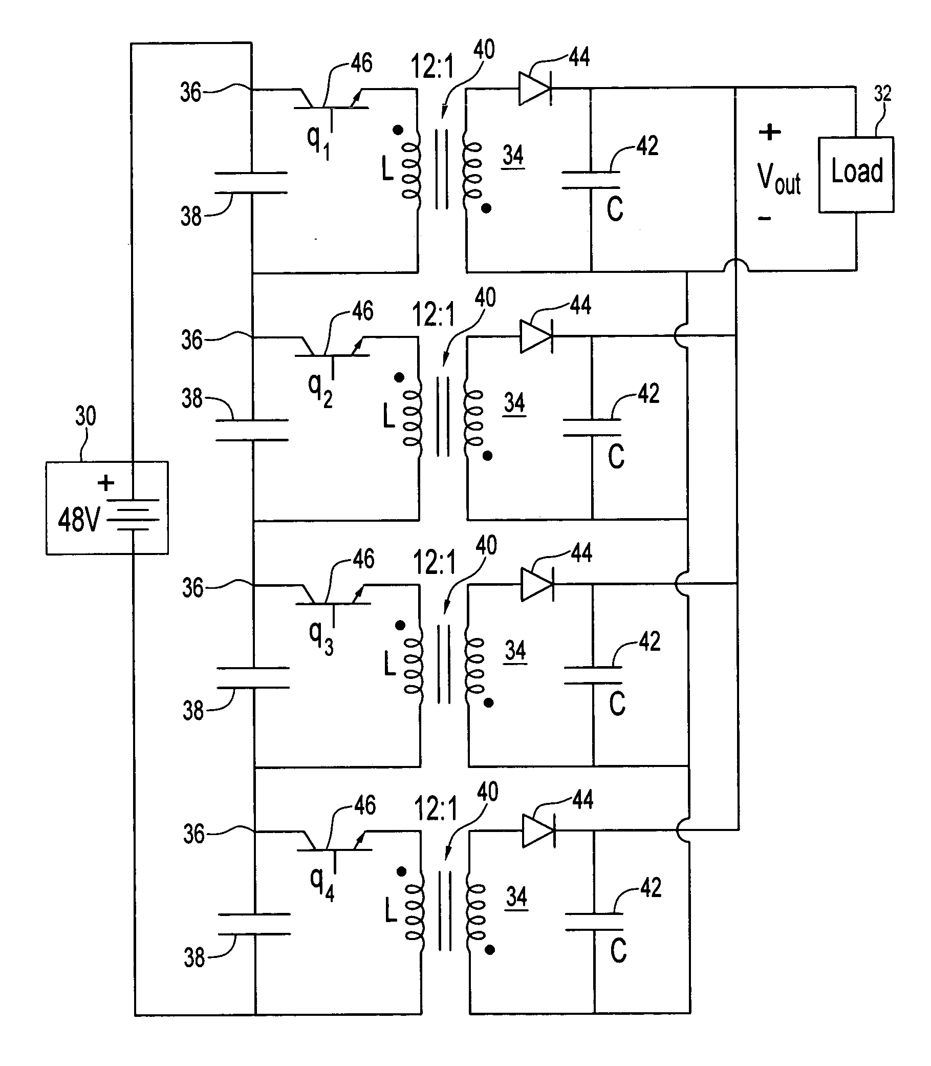
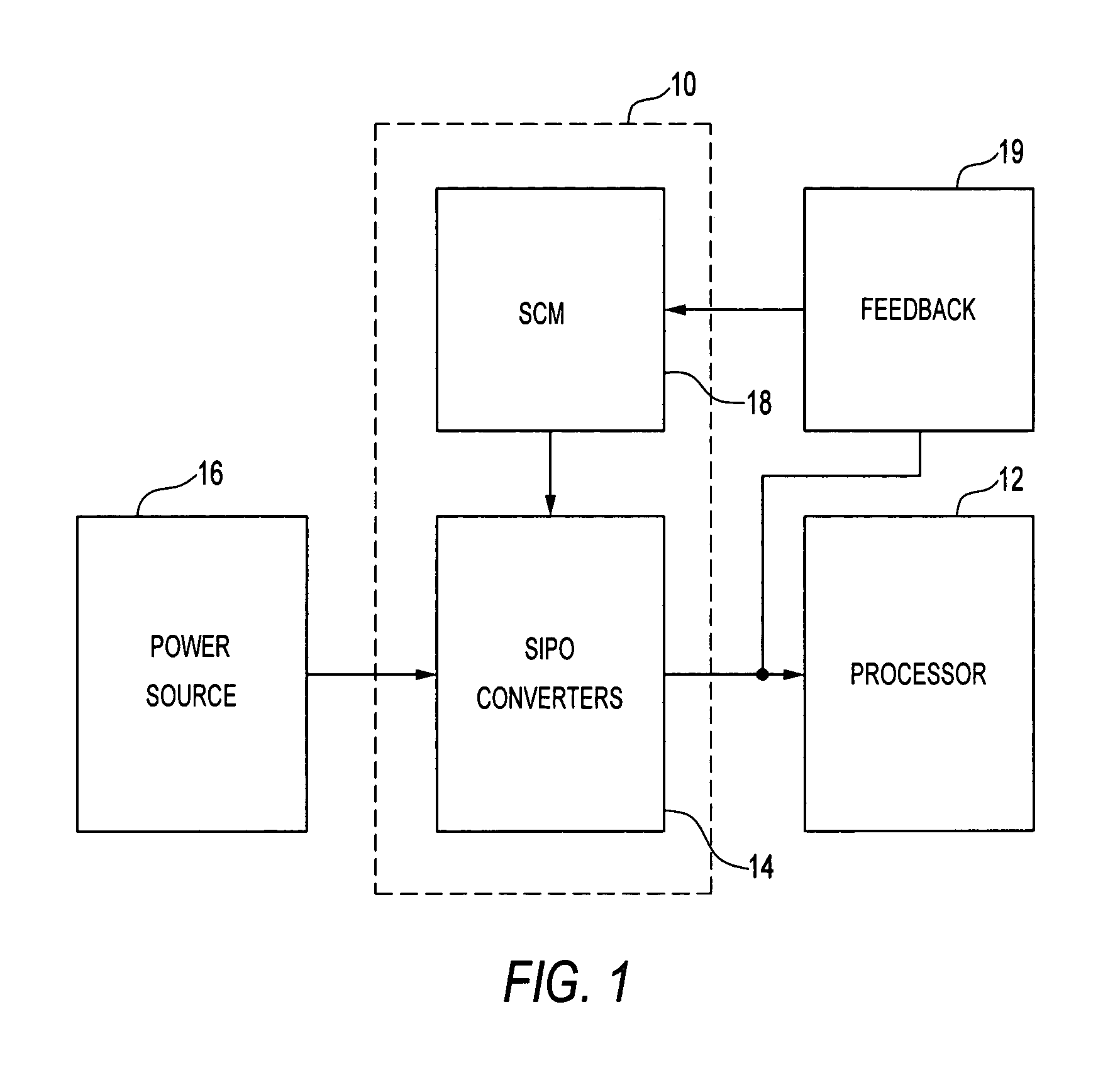
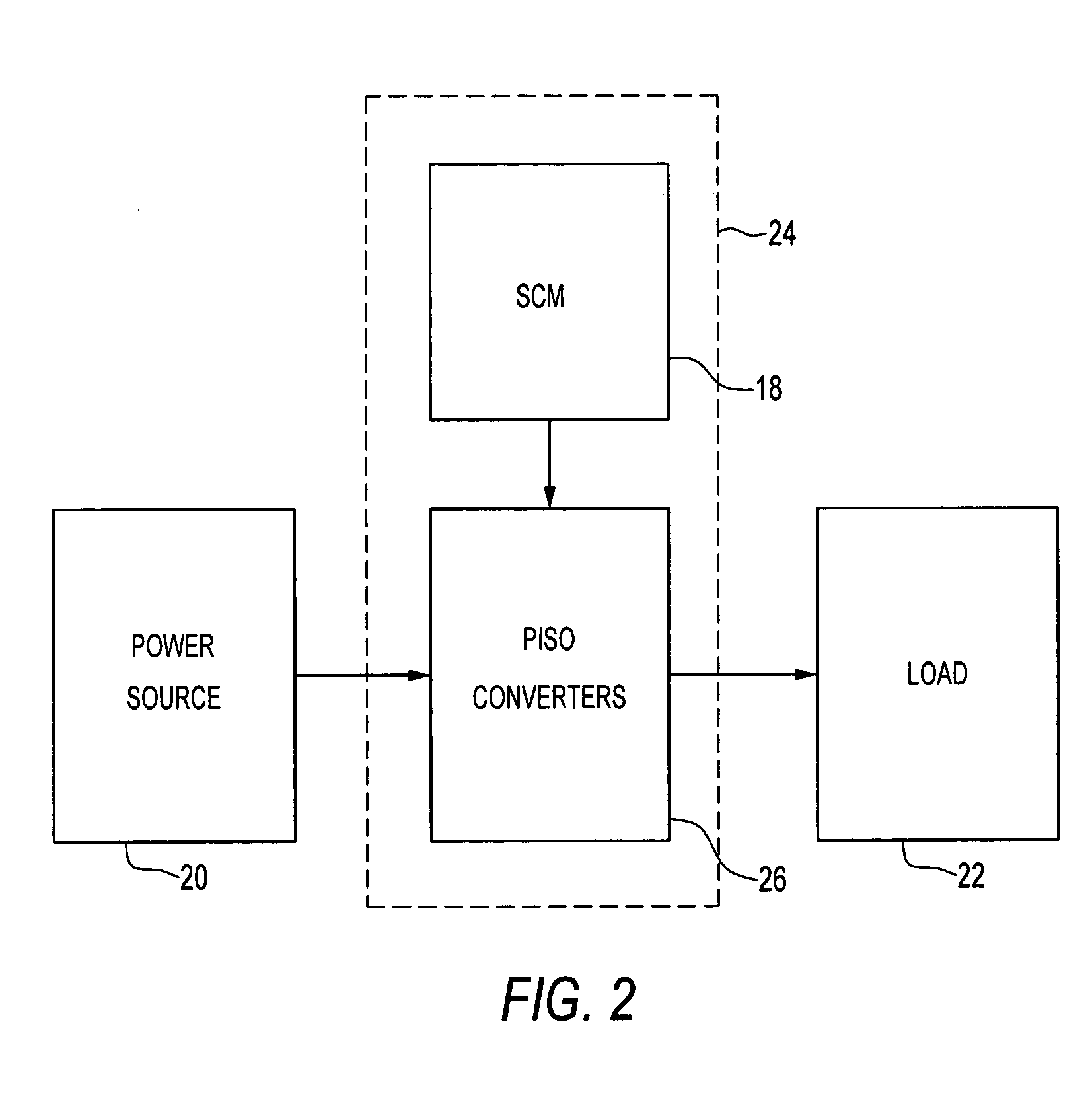
[0015] In preferred power supply embodiments of the invention, dc-dc switching converters make a substantial step up or step down in voltage while enforcing a sensorless current mode control that regulates output voltage and provides good dynamic current sharing. A preferred application of a step down embodiment of the invention is as a voltage regulator module that steps down a high voltage from a power source to a low voltage for a microprocessor. Good dynamic response may be realized, to potentially reduce the number of necessary filter capacitors, which are often used in conventional voltage regulator modules as a compromise for the poor dynamic response of current controlled voltage regulator modules that use a sensor to determine the voltage across an inductor serving as an output filter. A typical conventional arrangement is configured in multiple stages of parallel-input, parallel-output converters, and capacitors are used on the parallel-output to improve dynamic response. ...


PUM


Abstract

A power supply in an embodiment of the invention includes a plurality of dc-dc switching power converters, each of which has its input isolated from its output. The power converters are arranged with their respective inputs being series connected and their respective outputs being parallel connected in an embodiment of the invention. In another embodiment of the inputs are parallel connected and the outputs series connected. Each power converter includes an input filter in each of said dc-dc switching power converters and an output filter. Each power converter includes a sensorless current mode control circuit controlling its switching duty ratio.

Description

FIELD OF THE INVENTION [0001] The invention concerns switching power supplies. A power supply based on the invention may be used, for example, as a voltage regulation module, to step down voltage from a high voltage power source to a circuit or device, e.g., a microprocessor, or to step up voltage from a low voltage source, e.g., a fuel cell, to a load. BACKGROUND OF THE INVENTION [0002] Modern digital electronic circuits rely upon the delivery of significant currents to achieve required power for operation, as the trend has been toward lower voltages. This presents a dilemma in circuit design. Delivering high current loads, e.g., hundreds of amps, to printed circuit boards and integrated circuit devices can raise the cost of circuits. High current buses add significant expense to circuits and devices, but are generally necessary to deliver high current to printed circuit boards. [0003] Modern microprocessors highlight the trend toward delivery of high current loads. The Pentium® II...

Claims


Application Information

Patent Timeline
Patent Type & Authority Applications(United States)
IPC IPC(8): H02J1/10
CPCH02J1/108H02J1/102
Inventor KREIN, PHILIP T.
Owner THE BOARD OF TRUSTEES OF THE UNIV OF ILLINOIS
Why Eureka
Try Eureka