Injection mold and injection molding apparatus

a technology of injection molding and injection molds, which is applied in the field of injection molds and injection molding apparatuses for molding small and light optical elements, can solve the problems of weak pressure applied to the resin in the cavity, short supply of resin to compensate for shrinkage of the resin, and low accuracy of fine configuration of a surface and a smooth surface, so as to improve the accuracy of transfer and fine configuration , the effect of accurate smooth surfa

Inactive Publication Date: 2005-12-29
KONICA MINOLTA OPTO
View PDF8 Cites 10 Cited by
  • Summary
  • Abstract
  • Description
  • Claims
  • Application Information

AI Technical Summary

Benefits of technology

[0008] An object of the present invention is to provide an injection mold and an injection molding apparatus which inhibit resin in a gate from cooling down so as to improve in transfer accuracy and to ease a tensile stress caused by shrinkage of resin.
[0012] Since the injection mold and the injection molding apparatus according to the present invention have a heat-insulated gate, in a pressure retention process after a resin injection process, the resin in the gate is prevented from cooling down. Accordingly, solidification of the resin in the gate is delayed. This means maintaining the fluidity of resin in the gate, which permits a further supply of resin into the cavity in order to compensate shrinkage of resin in the cavity. Therefore, the molded product has an accurate fine configuration and an accurate smooth surface, that is, the transfer accuracy is improved. Also, the tensile stress applied to the center part of the product caused by shrinkage of the resin is eased, which prevents the product (optical element) from having a large birefringence. Consequently, a product (optical element) of high performance can be obtained.

Problems solved by technology

Therefore, the pressure applied to the resin in the cavity becomes weaker, and a supply of resin to compensate shrinkage of the resin becomes short.
Consequently, a molded product has problems that the accuracy of a fine configuration of a surface and the accuracy of a smooth surface are low (low transfer accuracy) and that since a tensile stress is applied to the center part of the product due to shrinkage of the resin, the birefringence of the lens becomes larger.
However, this mold does not solve the above-described problems, namely, a degradation in transfer accuracy caused by solidification of resin in the gate and an increase in tensil stress caused by shrinkage of resin in the cavity.

Method used


Image

  • Injection mold and injection molding apparatus
  • Injection mold and injection molding apparatus
  • Injection mold and injection molding apparatus

Examples


first embodiment

See FIGS. 1a, 1b and 2

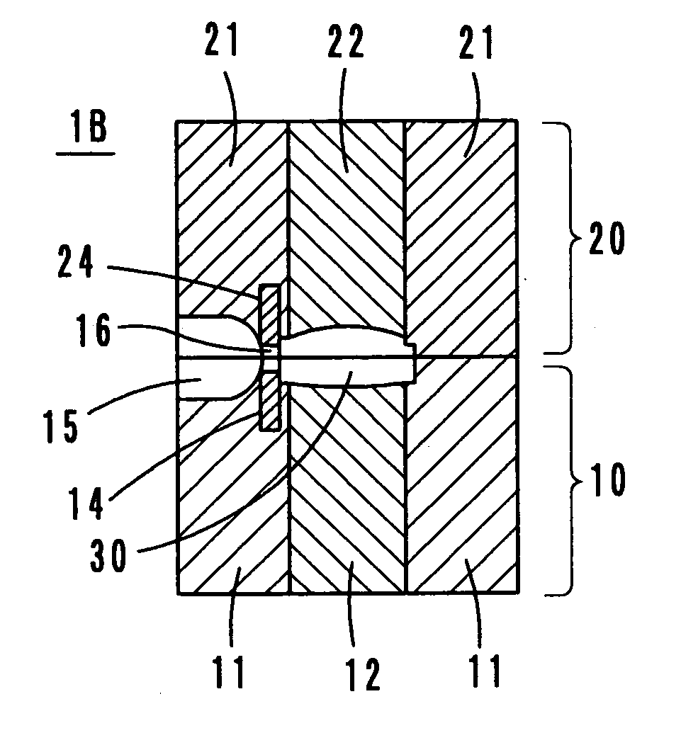
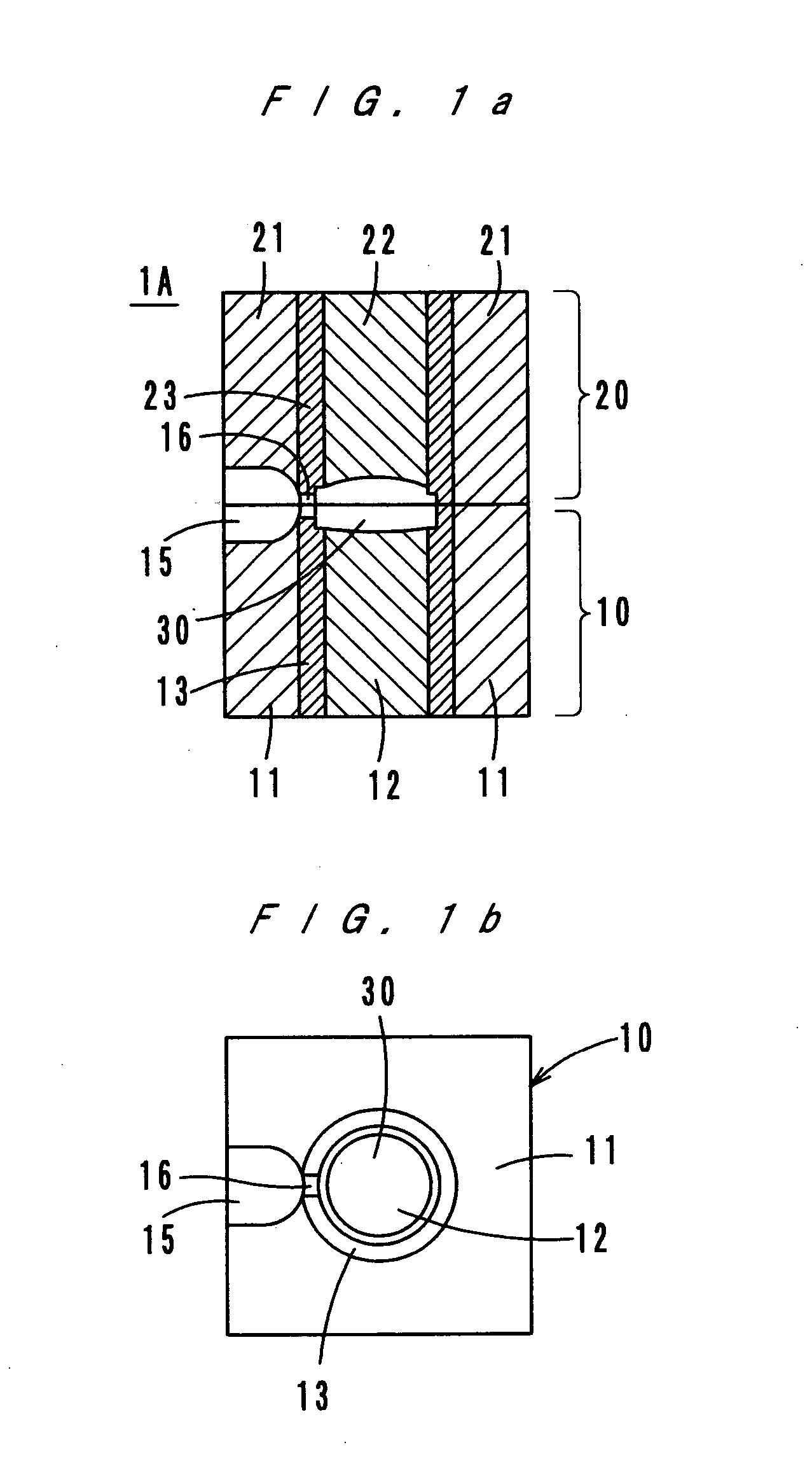
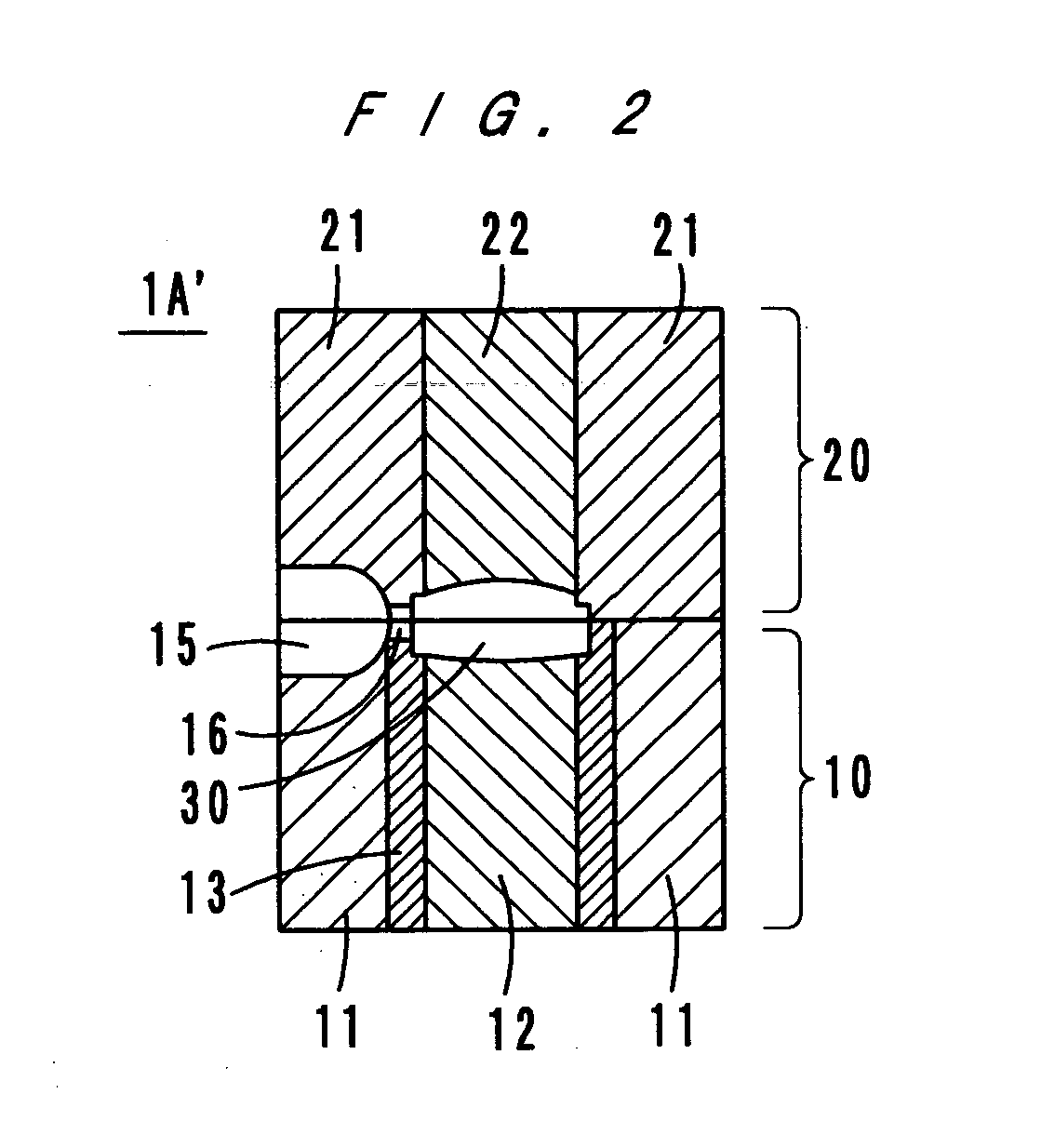
[0021] As FIGS. 1a and 1b show, a mold 1A according to a first embodiment of the present invention comprises a movable mold 10 and a fixed mold 20. The movable mold 10 comprises bases 11 and 12, and a sleeve-like heat insulator 13. The fixed mold 20 comprises bases 21 and 22, and a sleeve-like heat insulator 23. A cavity 30 is formed of mutually opposite end faces of the bases (cores) 12 and 22, and sides of the heat insulators 13 and 23.

[0022] A runner 15 is formed in the parting surface between the bases 11 and 21. A gate 16 is formed in the heat insulators 13 and 23 to be located between the runner 15 and the cavity 30. More specifically, the gate 16 is formed of recesses made in the mutually opposite end surfaces of the heat insulators 13 and 23.

[0023] The surface of the cavity 30 is finished in accordance with the configuration of a product, such as a lens, and the cavity 30 may have a surface processed layer of nickel plating.

[0024] The bases 11, 12, 2...

third embodiment

See FIGS. 4a and 4b

[0032]FIGS. 4a and 4b show a mold 1C according to a third embodiment of the present invention. In the mold 1C, a gate 16 is formed of recesses made in the mutually opposite end surfaces of the mold bases 11 and 21, and the inner surface of the gate 16 is coated with a heat insulator. The heat insulator coating may be a ceramic flame coating, a metal plating such as nickel, cobalt, etc., a titanium evaporation coating such as titanium nitride or a heat resistance polymer coating such as polyimide resin (with a coefficient of heat conductivity of 0.28 W / mK). For the bases 11, 12, 21 and 22, the materials named in the description of the first embodiment are usable.

[0033] Like the modification shown in FIG. 2, in the third embodiment also, it is possible to provide the heat insulating coating only for the movable mold 10. The effect of the present invention, which will be described later, is obtained by providing the heat insulating coating. The effect can be obtain...


PUM

PropertyMeasurementUnit
glass-transition temperatureaaaaaaaaaa

Abstract

An injection mold and an injection molding apparatus having a movable mold and a fixed mold. Each of the movable / fixed molds has bases, and a runner, a gate and a cavity are formed. The gate is composed of recesses made in mutually opposite end surfaces of sleeve-like heat insulators provided for the bases. Thereby, the gate is heat-insulated, and resin in the gate is prevented from cooling down during a pressure retention step. Thus, the resin keeps fluidity longer.

Description

[0001] This application is based on Japanese application No. 2004-191835 filed on Jun. 29, 2004, the content of which is herein incorporated by reference. BACKGROUND OF THE INVENTION [0002] 1. Field of the Invention [0003] The present invention relates to an injection mold and an injection molding apparatus, and more particularly to an injection mold and an injection molding apparatus for molding a small and light optical element, such as a lens. [0004] 2. Description of Related Art [0005] In recent years, with improvement of resin materials and injection molding techniques, small and light resin lenses have been developed, and a demand for use of these resin lenses as optical elements in optical pick-up devices and portable telephones has been stronger. In order to produce such resin lenses, molds which permit accurate transfer of fine configurations for diffraction elements and smooth surfaces or the like are required. [0006] Generally, a gate of a mold is narrow, and in a pressur...

Claims


Application Information

Patent Timeline
Patent Type & Authority Applications(United States)
IPC IPC(8): B29C33/38B29C33/56B29C45/26B29C45/27
CPCB29C33/3828B29C45/2708B29C33/56
Inventor SEKIHARA, KANJINAITO, ATSUSHIOKUMURA, YOSHIHIRO
Owner KONICA MINOLTA OPTO
Why Eureka
Try Eureka