[0020] Optionally, a stiffening treatment or a thickening or widening of the device is provided to prevent bending at locations and / or in directions where bending would otherwise be facilitated by the provision of the modifications.
[0022] In an exemplary embodiment of the invention, the device is designed to have a limited (e.g., at least for a particular applied force) extension of the non-planar sections. In an exemplary embodiment of the invention, the modified areas have a bending profile that is stepped, so that once a certain bending and / or twisting is achieved, further bending cannot take
advantage or takes lesser
advantage of the modification, thus preventing or reducing further
out of plane distortion. Alternatively or additionally, one or more struts or wires are provided to limit the relative movements (e.g., away and / or towards each other) of points on the device, thus limiting and / or otherwise controlling
out of plane motions. It should be noted that a series of modified areas may be used, each of which may each define one part of a bending profile, so that as a unit they define a complex bending profile.
[0024] In an exemplary embodiment of the invention, a
stent is provided having a cylindrical stent portion and a flaring portion. This stent is optionally used in a branching vessel stenosis situation, especially if the
branch is near perpendicular. The cylindrical section goes into the branching vessel and the flaring portion caps the bifircation area in the
main vessel. Optionally, the geometry of the flaring section (but not its orientation) is fixed using
coupling between the out-of-plane motion of various parts thereof. Optionally, the flaring portion defines a plurality of fingers. Alternatively or additionally, the flaring portion defines a mesh. The stent may be, for example, plastically, elastically, super-elastically deformed and / or use a shape memory mechanism. Optionally, the degree of flaring is limited to defining a cap having an internal angle of less than 180, for example, 170° or 160°, or any intermediate or smaller angle. This limitation may be useful to prevent strain on blood vessels in some anatomical and / or physiological situations.
[0028] In an exemplary embodiment of the invention, the stent is at least partially expanded before it is advanced all the way, such that a flaring part of the stent increases in
radius enough to assist in positioning the stent. Optionally, the stent is then expanded more, which may or may not affect the degree of flaring of the flaring portion, depending on its design. Alternatively or additionally, the
catheter comprises a
balloon or an extendible structure of another kind that, when extended, prevents axial advance into the side vessel beyond a desired amount.
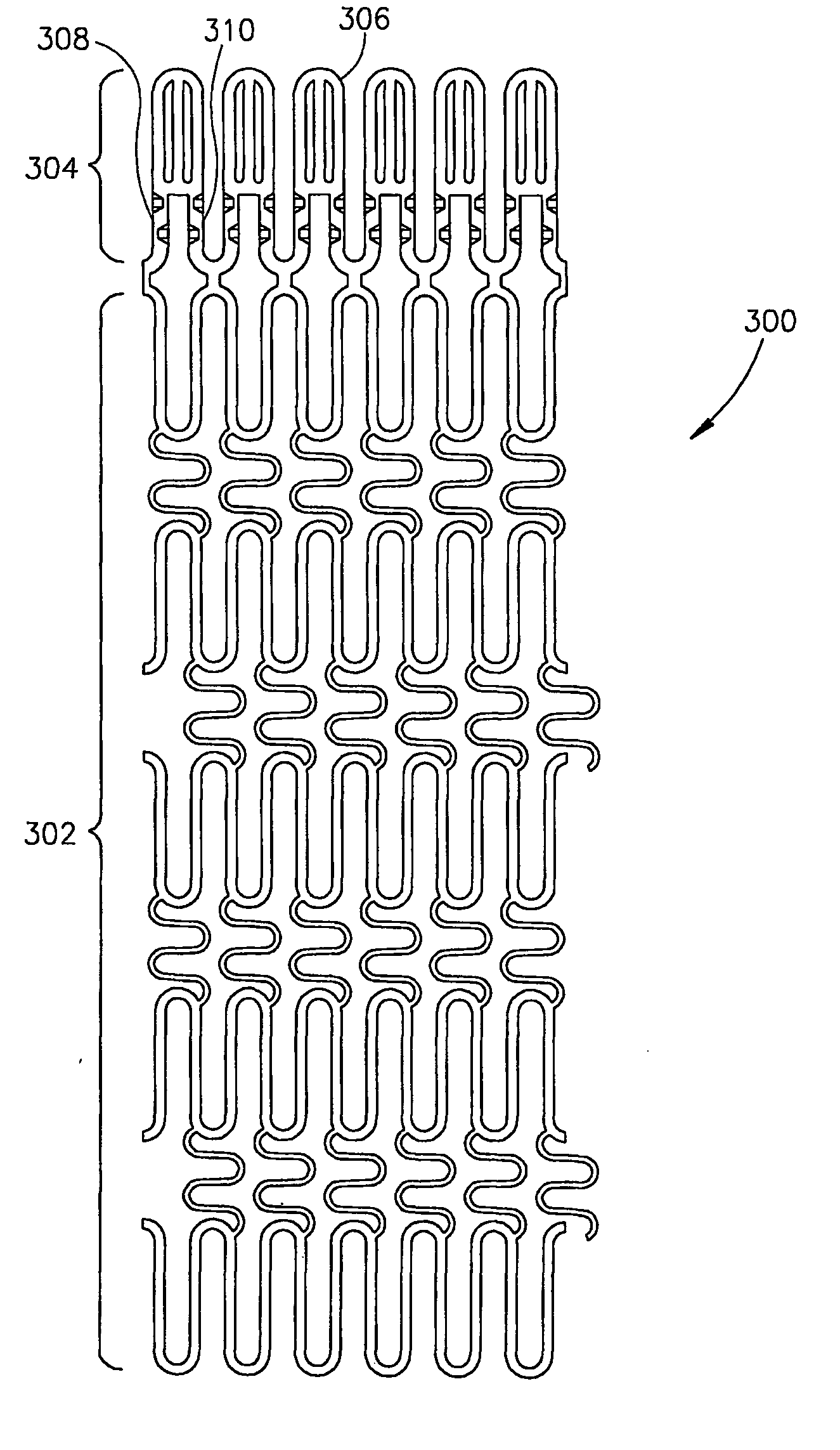
[0029] An aspect of some embodiments of the invention relates to a mesh stent having at least one end that is more readily expandable than a center and other end of the stent. In an exemplary embodiment of the invention, the mesh is designed to allow it to expand enough to
flare out to about or more than 90 degrees relative to an axis of the stent. In an exemplary embodiment of the invention, when the stent is expanded using a single long
balloon, the flaring portion expands first, for example, when a first
balloon pressure is reached and the rest of the stent expands when a second balloon pressure is reached. In an exemplary embodiment of the invention, the mesh sections of the stent comprise coiled or folded sections (e.g., folded in the device plane), to allow for a relatively greater expansion of the flaring portion.

