Internal fixation element for hip acetabular shell

a technology of acetabular shell and fixation element, which is applied in the field of orthopaedics, can solve the problems that the support ring must be used in all applications, and achieve the effects of reducing cross-section, facilitating deformation, and facilitating bending

Inactive Publication Date: 2005-12-29
HOWMEDICA OSTEONICS CORP
View PDF47 Cites 77 Cited by
  • Summary
  • Abstract
  • Description
  • Claims
  • Application Information

AI Technical Summary

Benefits of technology

[0009] Further, the present invention provides a shell member for use in an acetabular cup assembly having an internal polymeric bearing member for securement within the shell member. The internal polymeric bearing member being selected from a plurality of bearing members having different characteristics such as bearing surface size and inclination. The shell member includes an internal wall of the cavity with a coupling element on the internal wall cavity of the shell member. The coupling element is compatible with the external securing characteristics of at least one of the plurality of internal bearing members. Optionally, a second additional bearing coupling element may be provided within the cavity of the shell member, the second securing element being compatible with the securing characteristics of at least another of the plurality of internal bearing members. The first coupling element and the second optional coupling element being juxtaposed with one another and placed at relative locations such that the effectiveness of each of the first and second securing elements is maintained in the presence of the other of the first and second securing elements, whereby the one and the another of the internal bearing members each is selectable for effective securement within the shell member to complete the acetabular cup assembly.
[0014] The wing, flange or strap is deformable at least in a direction perpendicular to the radial direction and may be oriented at various angles and extended various lengths with respect to the body of the adaptor. Obviously, the longer the length, the greater engagement with various areas of the pelvis are possible. The wing, strap or flange may include a reduced cross-section to facilitate deformation or may be made of a ductile material. Alternately, the flange can have a groove or series of grooves to facilitate bending.

Problems solved by technology

This construction has a disadvantage that the support ring must be used in all applications since it receives the outer shell of the acetabular prosthesis.

Method used


Image

  • Internal fixation element for hip acetabular shell
  • Internal fixation element for hip acetabular shell
  • Internal fixation element for hip acetabular shell

Examples


Embodiment Construction

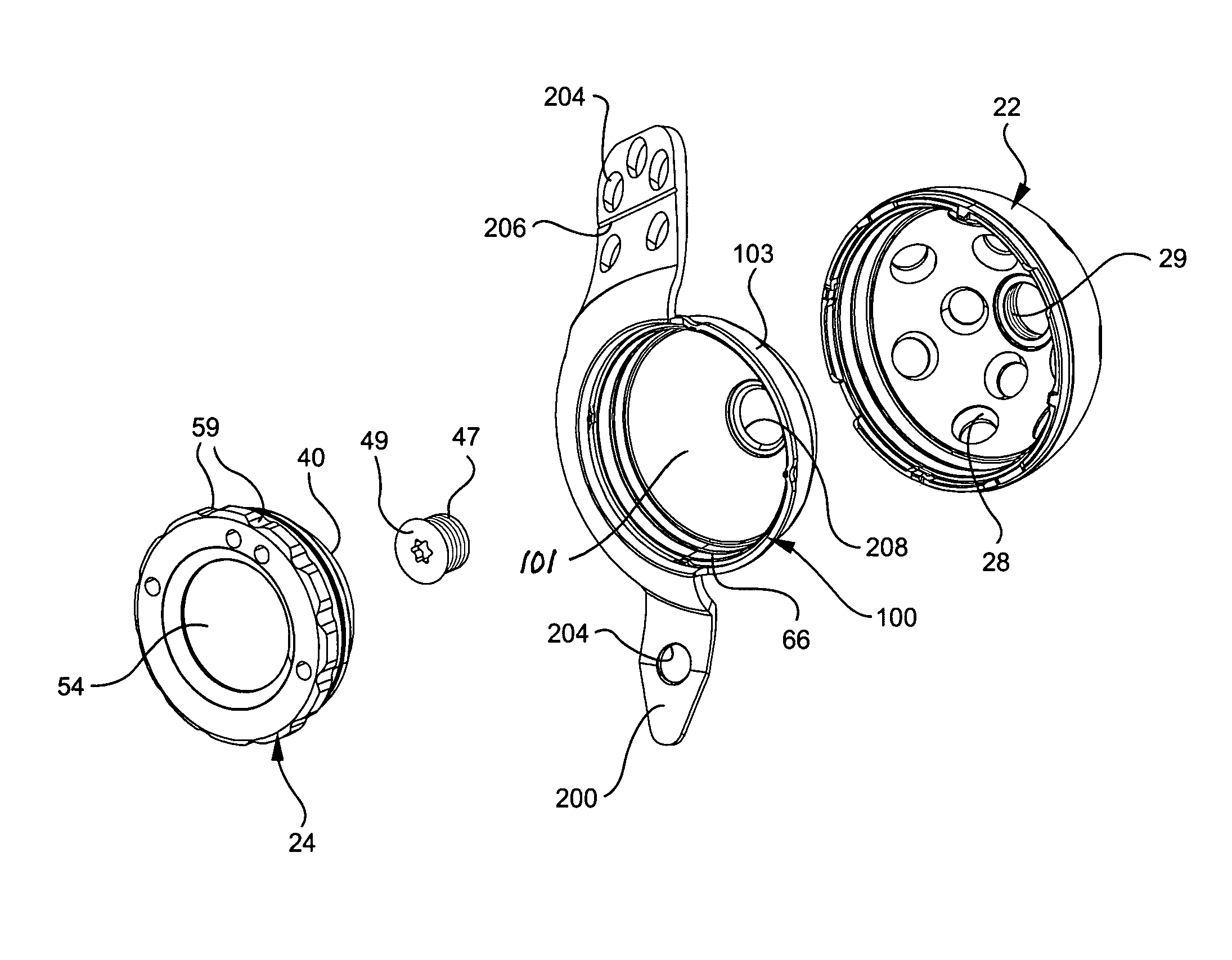
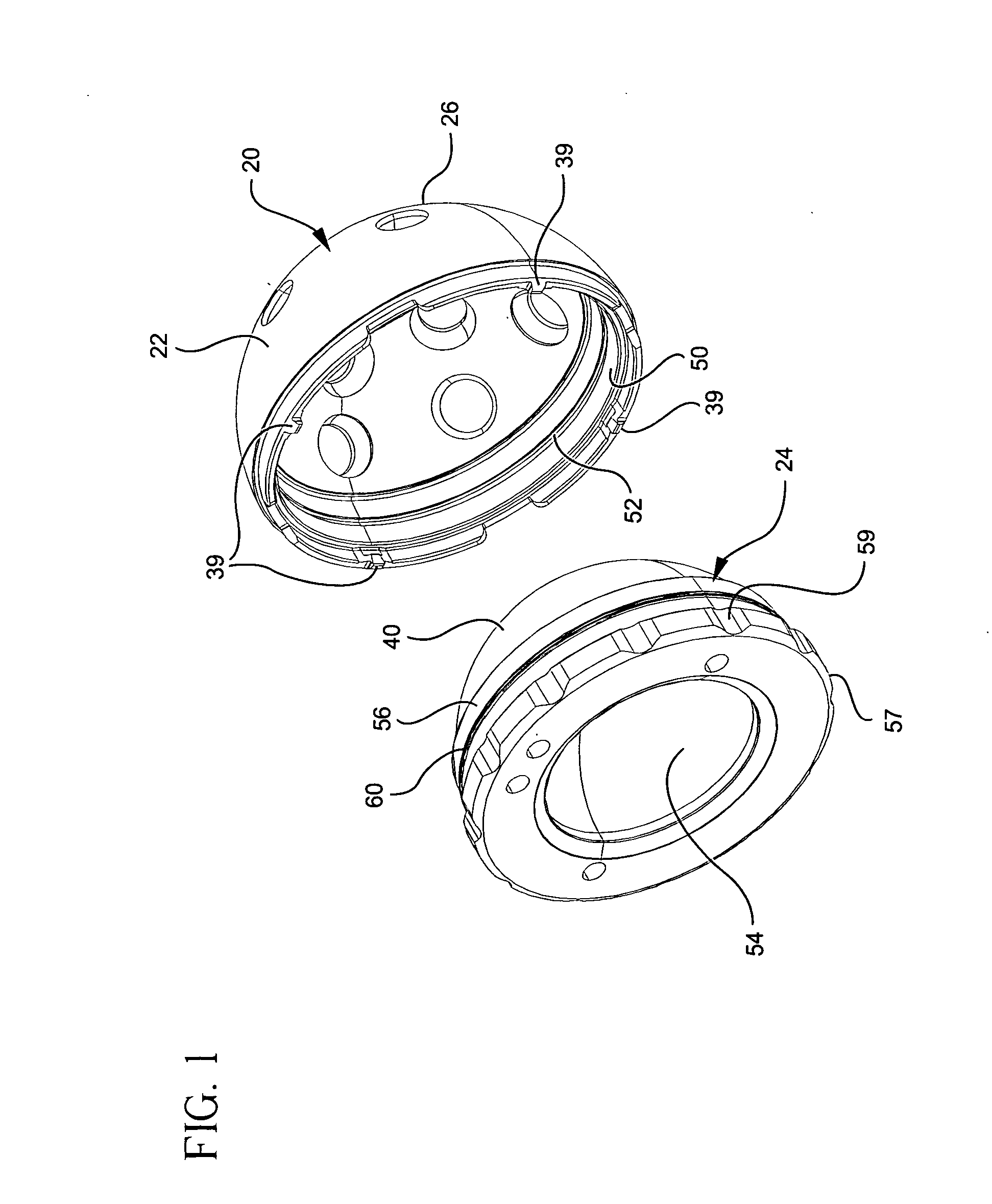
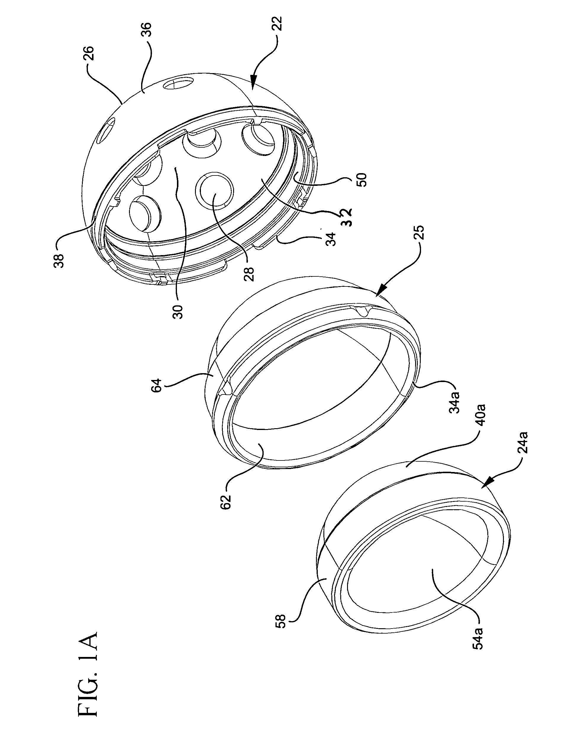
[0034] Referring now to the figures, and especially to FIG. 1 there is shown an acetabular cup assembly constructed in accordance with the present invention is illustrated generally as 20. Acetabular cup assembly 20 includes a shell component in the form of metallic shell member 22 and a bearing insert which may be in the form of a plastic (ultra-high molecular weight polyethylene) bearing member 24 as shown in FIG. 1. Alternately, the bearing, as shown in FIG. 1A, may be a ceramic bearing 24a. If a ceramic bearing is used, a metal adaptor 25 may be used (see FIG. 1A). Shell member 22 includes an outer surface 26 having a hemispherical profile configuration which enables shell member 22 to be seated and fixed in place within an appropriately prepared acetabulum in a well-known manner such as by use of bone cement or bone screws. A plurality of screw holes 28 are provided in shell member 22 for receiving anchoring screws (not shown) when such supplemental securing means are desired. ...


PUM


Abstract

An acetabular cup assembly for a prosthetic hip joint includes an outer shell for attachment to the acetabulum. The outer shell has an inner surface receiving a bearing insert portion. Complimentary coupling features are provided on the inner surface of the outer shell and the outer surface of the bearing insert for coupling the bearing insert to the outer shell. A plurality of adaptors are provided having an outer surface for engaging an inner surface of the outer shell and having an inner surface for receiving the bearing insert. Each adaptor has at least one radial extending strap or flange for engaging the bone surrounding the acetabulum. The straps or flanges may be of different sizes and shapes and may be at different locations on the adapter. The inner surface of the adaptor includes the same coupling features as the shell so as to be able to receive a bearing insert.

Description

BACKGROUND OF THE INVENTION [0001] This invention relates generally to orthopedics and, in particular, to a versatile reconstruction system associated with an acetabular prosthetic implant. [0002] The replacement of members of a natural hip joint with prosthetic implants has become widespread and is being accomplished with ever-increasing frequency. The variety of conditions encountered when effecting such implants has led to the use of various bearing materials and attachment methods placed at an optimum position and orientation, as determined by conditions encountered at the site of the implant. The choice of a particular material for the bearing, as well as the size, positioning and orientation of the bearing member, is determined by the surgeon performing the procedure. Usually such choices are made on the basis of a pre-operative assessment of the needs of a particular patient; however, at times the choices are not completed until the implant site actually is being prepared and...

Claims


Application Information

Patent Timeline
Patent Type & Authority Applications(United States)
IPC IPC(8): A61B17/86A61F2/00A61F2/30A61F2/32A61F2/34A61F2/46
CPCA61B17/86A61F2310/00179A61F2/34A61F2002/30332A61F2002/30367A61F2002/30382A61F2002/30405A61F2002/30433A61F2002/30487A61F2002/30578A61F2002/30604A61F2002/30607A61F2002/30616A61F2002/30787A61F2002/3401A61F2002/3403A61F2002/3404A61F2002/3411A61F2002/343A61F2002/3432A61F2002/3448A61F2002/3451A61F2002/4631A61F2220/0025A61F2220/0033A61F2220/0041A61F2250/0062A61F2310/00011A61F2310/00023A61F2/30744A61F2002/30331A61F2002/305A61F2002/3054
Inventor DONG, NICHOLAS NAI GUANGMELDRUM, RUSSELL DONKREBS, VIKTOR ERIK
Owner HOWMEDICA OSTEONICS CORP
Why Eureka
Try Eureka