Semi-automated computer-implemented method and system for designing manifold assemblies

a computer-implemented and assembly technology, applied in computer-aided design, manufacturing tools, instruments, etc., can solve the problems of consuming a substantial amount of man-hours, bottlenecking the detailing, and the conventional design process takes about six to seven weeks to complete, so as to minimize the overall heater gap, minimize the number of zones, and minimize the effect of the heater number

Inactive Publication Date: 2005-12-29
PLASTIC ENG & TECHN SERVICES
View PDF6 Cites 10 Cited by
  • Summary
  • Abstract
  • Description
  • Claims
  • Application Information

AI Technical Summary

Benefits of technology

[0010] According to a first embodiment of the present invention, a semi-automated computer-implemented method for designing manifold assemblies is disclosed. The method includes receiving a number of design parameters for the design of a manifold assembly and applying the number of design parameters to a heater and zoning logic to generate a manifold assembly design. The method can further include generating two-dimensional data for the manifold assembly based on the number of design parameters and the heater and zoning logic. The method can further include automatically generating a blueprint based on the two-dimensional data for the manifold assembly. In certain embodiments, the manifold assembly design includes a three-dimensional rendering of the manifold assembly. The method can further include automatically generating a bill of materials based on the two-dimensional data for the manifold assembly. The number of design parameters can include manifold size, sprue coordinates, and drop coordinates. The heater and zoning logic can include minimizing overall heater gap, minimize number of zones, and minimize number of heaters. The manifold assembly design can include a manifold, one or more drops, one or more heaters, one or more thermocouples, and one or more plugs.
[0011] According to a second embodiment of the present invention, a semi-automated computer-implemented system for designing manifold assemblies is disclosed. The system can include one or more computers. The one or more computers can be configured to receive a number of design parameters for the design of a manifold assembly and apply the number of design parameters to a heater and zoning logic to generate a manifold assembly design. The one or more computers can be further configured to generate two-dimensional data for the manifold asse

Problems solved by technology

Overall, the conventional design process takes about six to seven weeks to complete.
This conversion consumes a substantial amount

Method used


Image

  • Semi-automated computer-implemented method and system for designing manifold assemblies
  • Semi-automated computer-implemented method and system for designing manifold assemblies
  • Semi-automated computer-implemented method and system for designing manifold assemblies

Examples


Embodiment Construction

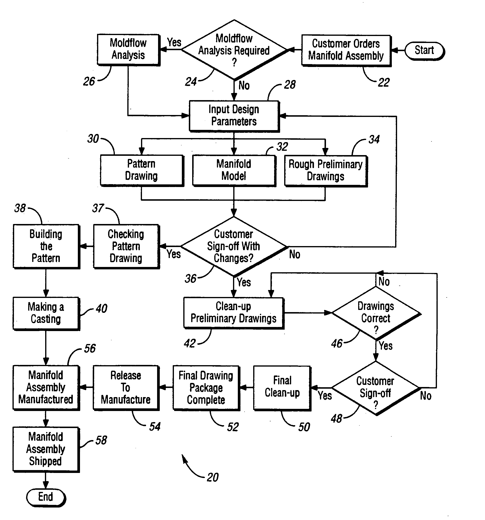
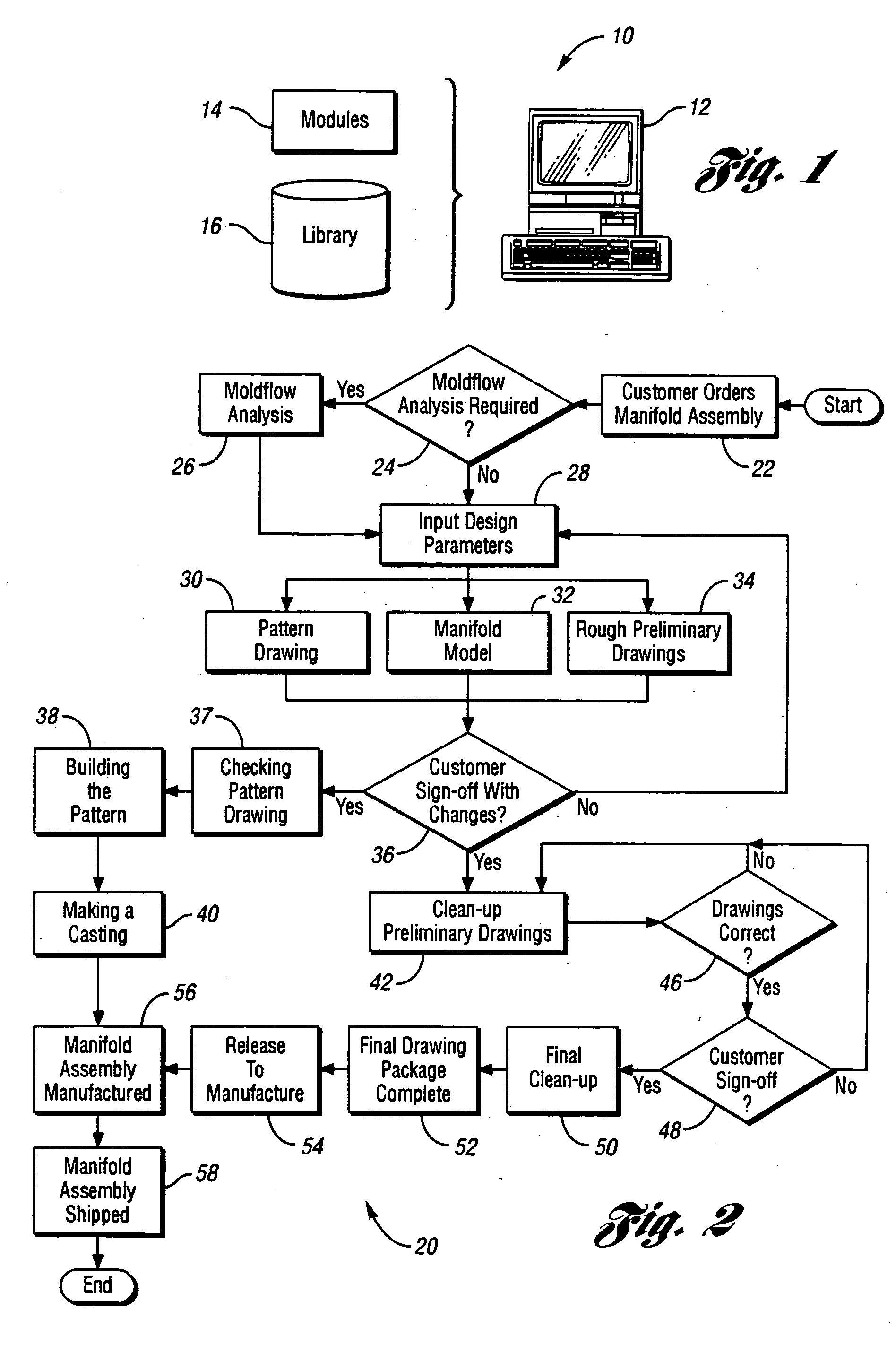
[0029] The methods and systems of the present invention operate in the environment of manifold assembly design. Elements of a manifold assembly, include, but are not limited to, manifolds, heaters, thermocouples, pressure pads / preload plates, plugs, location rings, and drops. Manifolds are usually sand castings with raised bosses on both sides for drops, sprue, and pressure pads. Manifold types, include, but are not limited to, round manifolds (either two inch or three inch) and square manifolds. The pattern for the manifold can be a group of straight-line segments joining the sprue to each drop, or joining the sprue to an intermediate branch point that is joined to one or more drops. Straight segments are gun drilled to allow flow through the manifold. In certain embodiments, there can between about 1 to 120 drops per manifold.

[0030] Heaters are flat metal pads bent into a substantially circular form (for round castings, round stainless steel P-20 or H-13, or any other mold steel)...


PUM

PropertyMeasurementUnit
Sizeaaaaaaaaaa

Abstract

A semi-automated computer-implemented method for designing manifold assemblies. The method can include receiving a number of design parameters for the design of a manifold assembly and applying the number of design parameters to a heater and zoning logic to generate a manifold assembly design.

Description

BACKGROUND OF THE INVENTION [0001] 1. Field of the Invention [0002] One aspect of the present invention relates to a semi-automated computer-assisted method and system for designing manifold assemblies, and more specifically, hot runner manifold assemblies. [0003] 2. Background Art [0004] Hot runner manifold assemblies are used to deliver molten plastic into injection molds. A hot runner manifold can be comprised of a steel casing that distributes molten plastic, wood or steel, or mixtures thereof, from the outlet of a molding machine to the mold. Examples of steel casings include, but are not limited to, cast round, square, or rectangular; and machined round, square, or rectangular. Plastic enters the manifold through one or more sprue bushings and exits to the mold through one or more drops. One or more valve gates may be used to control the flow through the one or more drops. The manifold is typically retained by compression between the molding machine and the mold steel. The man...

Claims


Application Information

Patent Timeline
IPC IPC(8): B29C33/38B29C45/27G06F17/50G06F19/00
CPCB29C33/3842B29C45/2725G06F2217/80G06F2217/41G06F17/50G06F30/00G06F2113/22G06F2119/08
Inventor TOOMAN, PATRICK A.CASEY, BRUCE J.DURAND, ROBERTOTLEWSKI, EDWARD
Owner PLASTIC ENG & TECHN SERVICES
Why Eureka
Try Eureka